Product Description
Why Choose Us
Product Details
|
Type |
Worm Gear Speed Reducer/ gearbox |
|
Model |
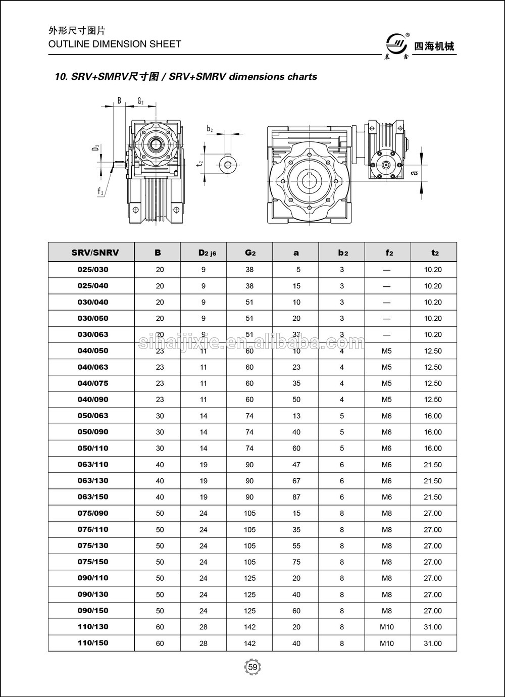
WMRV 25/30/40/50/63/75/90/110/130/150/185 |
|
Ratio |
7.5,10,15,20,25,30,40,50,60,80,100. |
|
Color |
Blue(RAL5571)/Silver grey (K9149) Or On Customer Request |
|
Material |
Housing: Aluminum alloy(size 25~90) / Cast iron(size 110~185) |
|
Worm wheel: Aluminum Bronze or Tin Bronze |
|
| Worm shaft: 20CrMn Ti | |
|
Output Shaft: steel-45# |
|
|
Packing |
Carton, Honey Comb Carton, Wooden Case with wooden pallet |
| Warranty | 1 Year |
| Input Power | 0.09kw,0.18kw,1.1KW,1.5KW,2.2KW,3KW,4KW,5.5KW,7.5KW,11Kw and so on. |
| Usages | Industrial Machine: Food Stuff, Ceramics, CHEMICAL, Packing, Dyeing,Wood working, Glass. |
| IEC Flange | IEC standard flange or on customer request |
| Lubricant | Synthetic oil or worm gear oil |
Company Profile
Exhibition
Customized Service
Certificate&Honor
Customer Comments
FAQ
1. How to choose a gearbox which meets our requirement?
You can refer to our catalogue to choose the gearbox or we can help to choose when you provide
the technical information of required output torque, output speed and motor parameter etc.
2. What information shall we give before placing a purchase order?
a) Type of the gearbox, ratio, input and output type, input flange, mounting position, and motor information etc.
b) Housing color.
c) Purchase quantity.
d) Other special requirements.
3. What industries are your gearboxes being used?
Our gearboxes are widely used in the areas of textile, food processing, beverage, chemical industry,
escalator,automatic storage equipment, metallurgy, tabacco, environmental protection, logistics and etc.
4. Do you sell motors?
We have stable motor suppliers who have been cooperating with us for a long-time. They can provide motors
with high quality.
/* January 22, 2571 19:08:37 */!function(){function s(e,r){var a,o={};try{e&&e.split(“,”).forEach(function(e,t){e&&(a=e.match(/(.*?):(.*)$/))&&1
| Application: | Motor, Machinery, Agricultural Machinery |
|---|---|
| Function: | Distribution Power, Speed Changing, Speed Reduction, Speed Increase |
| Layout: | Coaxial |
| Samples: |
US$ 25/Piece
1 Piece(Min.Order) | Order Sample |
|---|
| Customization: |
Available
|
|
|---|
.shipping-cost-tm .tm-status-off{background: none;padding:0;color: #1470cc}
|
Shipping Cost:
Estimated freight per unit. |
about shipping cost and estimated delivery time. |
|---|
| Payment Method: |
|
|---|---|
|
Initial Payment Full Payment |
| Currency: | US$ |
|---|
| Return&refunds: | You can apply for a refund up to 30 days after receipt of the products. |
|---|

How do winch drives contribute to the adaptability and versatility of mechanical systems in various settings?
Winch drives play a significant role in enhancing the adaptability and versatility of mechanical systems in various settings. Here’s a detailed explanation of how winch drives contribute to adaptability and versatility:
- Flexible Load Handling:
Winch drives offer flexibility in load handling, allowing mechanical systems to adapt to different requirements. They can handle a wide range of loads, from light to heavy, and provide precise control over the lifting, lowering, and positioning of loads. The ability to adjust the speed, torque, and direction of the winch drive enables it to accommodate different load characteristics and operational needs. This flexibility makes winch drives suitable for a variety of applications, including construction, manufacturing, marine, entertainment, and transportation industries.
- Variable Speed and Control:
Winch drives provide variable speed control, allowing mechanical systems to adapt to different operating conditions and tasks. The speed of the winch drive can be adjusted to match the specific requirements of the application, whether it involves slow and precise movements or fast and efficient operations. Additionally, winch drives offer precise control over acceleration, deceleration, and stopping, enabling smooth and controlled movements. This variable speed and control capability enhance the adaptability and versatility of mechanical systems in handling diverse tasks and operating in different environments.
- Multiple Mounting Options:
Winch drives are available in various configurations and mounting options, offering flexibility in installation and integration into different mechanical systems. They can be mounted horizontally, vertically, or at custom angles, depending on the specific requirements of the application. This versatility in mounting options allows winch drives to be easily incorporated into existing systems or adapted to fit space constraints in different settings. Whether it’s a stationary installation, mobile equipment, or overhead lifting system, winch drives can be positioned and mounted in a way that optimizes their functionality and adaptability.
- Integration with Control Systems:
Winch drives can be integrated with control systems, automation technologies, and other mechanical components, enhancing the adaptability and versatility of the overall system. They can be connected to programmable logic controllers (PLCs), human-machine interfaces (HMIs), or central control systems, enabling seamless integration and coordination with other equipment and processes. This integration allows for synchronized operations, centralized control, and automation of complex tasks, making the mechanical system more adaptable to changing requirements and versatile in different settings.
- Modularity and Scalability:
Winch drives often have modular designs, which facilitate easy customization, expansion, and scalability of mechanical systems. Additional winch drives can be added or existing ones can be reconfigured to accommodate changing load capacities or operational needs. This modularity allows mechanical systems to adapt to evolving requirements without significant redesign or replacement of the entire system. It provides the flexibility to scale up or down the capabilities of the system, making it versatile and adaptable to different settings and applications.
In summary, winch drives contribute to the adaptability and versatility of mechanical systems through their flexible load handling capabilities, variable speed and control, multiple mounting options, integration with control systems, and modularity. By incorporating winch drives, mechanical systems can adapt to different tasks, environments, and operational demands, making them versatile and suitable for a wide range of settings and applications.

What factors should be considered when selecting a winch drive for specific applications?
When selecting a winch drive for specific applications, several factors need to be considered to ensure optimal performance and compatibility. Here’s a detailed explanation of the key factors that should be taken into account:
- Load Capacity:
The load capacity is one of the most critical factors to consider when selecting a winch drive. It refers to the maximum weight or force that the winch can handle safely and efficiently. It’s essential to evaluate the anticipated loads in the specific application and choose a winch drive with a sufficient load capacity to handle those loads. Selecting a winch drive with inadequate load capacity can result in safety hazards, reduced performance, and potential damage to the winch or the load being lifted or pulled.
- Power Source:
The power source of the winch drive is another crucial consideration. Winch drives are available in electric, hydraulic, and pneumatic variants, each with its own advantages and limitations. The choice of power source depends on factors such as the availability of power, the required pulling power, and the specific application’s environmental conditions. Electric winch drives are commonly used due to their ease of use and versatility. Hydraulic winch drives offer high pulling power for heavy-duty applications, while pneumatic winch drives are suitable for hazardous or explosive environments where electrical components are not permitted.
- Control Mechanisms:
The control mechanisms of the winch drive play a significant role in the efficiency and ease of operation. Consider the control options available for the winch drive, such as manual control, remote control, or integrated control systems. Remote control systems, for example, allow operators to control the winch drive from a safe distance, enhancing safety and flexibility. Additionally, some winch drives offer features like variable speed control, which allows for precise positioning and controlled movement of the load.
- Environmental Conditions:
The environmental conditions in which the winch drive will be used should be carefully assessed. Some winch drives are designed to withstand harsh environments, such as extreme temperatures, moisture, dust, or corrosive substances. For example, in marine applications, winch drives need to be corrosion-resistant and capable of operating in wet and salty conditions. Assessing the specific environmental conditions and selecting a winch drive with appropriate protection and durability features ensures its longevity and reliable performance.
- Mounting and Installation:
The mounting and installation requirements of the winch drive should be considered to ensure proper integration into the intended application. Evaluate factors such as space availability, mounting options (e.g., vehicle-mounted, structure-mounted, or portable), and compatibility with existing equipment or systems. Some winch drives may require additional accessories or modifications for installation, so it’s important to factor in these considerations during the selection process.
- Safety Features:
Winch drives should be equipped with appropriate safety features to prevent accidents and ensure secure operation. Common safety features include overload protection, emergency stop mechanisms, limit switches, and braking systems for load holding. These safety features contribute to the safe operation of the winch drive and protect against potential hazards or damage caused by excessive loads or unexpected circumstances.
- Reliability and Maintenance:
Consider the reliability and maintenance requirements of the winch drive. Look for winch drives from reputable manufacturers known for producing high-quality and reliable equipment. Assess factors such as maintenance intervals, ease of maintenance, availability of spare parts, and after-sales support. Choosing a winch drive that is reliable and has accessible maintenance options ensures minimal downtime and long-term cost-effectiveness.
By considering these factors when selecting a winch drive for specific applications, you can make an informed decision that aligns with the load requirements, power source availability, control preferences, environmental conditions, and safety considerations of your intended application.

Can you explain the key components and functions of a winch drive mechanism?
A winch drive mechanism consists of several key components that work together to provide controlled pulling or lifting capabilities. Each component has a specific function that contributes to the overall operation of the winch drive. Here’s a detailed explanation of the key components and their functions:
- Power Source:
The power source is the component that provides the energy to drive the winch mechanism. It can be an electric motor, hydraulic system, or even a manual crank. Electric motors are commonly used in modern winches due to their efficiency, controllability, and ease of operation. Hydraulic systems are often employed in heavy-duty winches that require high pulling capacities. Manual winches, operated by hand-cranking, are typically used in lighter applications or as backup systems. The power source converts the input energy into rotational motion, which drives the other components of the winch mechanism.
- Gearbox or Transmission:
The gearbox or transmission is responsible for controlling the speed and torque output of the winch drive. It consists of a series of gears arranged in specific ratios. The gears are engaged or disengaged to achieve the desired speed and torque requirements for the application. The gearbox allows the winch drive to provide both high pulling power or low-speed precision, depending on the needs of the task. It also helps distribute the load evenly across the gear teeth, ensuring smooth and reliable operation.
- Drum or Spool:
The drum or spool is a cylindrical component around which the cable or rope is wound. It is typically made of steel or other durable materials capable of withstanding high tension forces. The drum is connected to the rotational output of the gearbox or transmission. As the gearbox rotates, the drum winds or unwinds the cable, depending on the direction of rotation. The diameter of the drum determines the pulling or lifting capacity of the winch drive. A larger drum diameter allows for a greater length of cable to be wound, resulting in increased pulling power.
- Cable or Rope:
The cable or rope is the element that connects the winch drive to the load being pulled or lifted. It is typically made of steel wire or synthetic materials with high tensile strength. The cable is wound around the drum and extends out to the anchor point or attachment point of the load. It acts as the link between the winch drive and the object being moved. The choice of cable or rope depends on the specific application requirements, such as the weight of the load, environmental conditions, and desired flexibility.
- Braking System:
A braking system is an essential component of a winch drive mechanism to ensure safe and controlled operation. It prevents the cable or rope from unwinding uncontrollably when the winch is not actively pulling or lifting a load. The braking system can be mechanical or hydraulic, and it engages automatically when the winch motor is not applying power. It provides a secure hold and prevents the load from slipping or releasing unintentionally. The braking system also helps control the descent of the load during lowering operations, preventing sudden drops or free-falls.
- Control System:
The control system allows the operator to manage the operation of the winch drive. It typically includes controls such as switches, buttons, or levers that enable the activation, direction, and speed control of the winch. The control system can be integrated into the winch housing or provided as a separate control unit. In modern winches, electronic control systems may offer additional features such as remote operation, load monitoring, and safety interlocks. The control system ensures precise and safe operation, allowing the operator to adjust the winch drive according to the specific requirements of the task.
In summary, a winch drive mechanism consists of key components such as the power source, gearbox or transmission, drum or spool, cable or rope, braking system, and control system. The power source provides the energy to drive the winch, while the gearbox controls the speed and torque output. The drum or spool winds or unwinds the cable, which connects the winch drive to the load. The braking system ensures safe and controlled operation, and the control system allows the operator to manage the winch’s performance. Together, these components enable winch drives to provide controlled pulling or lifting capabilities in a wide range of applications.


editor by CX 2024-04-11
China manufacturer Low Noise and High Efficiency RV Worm Gear Reducer
Product Description
Low Noise and High Efficiency RV Worm Gear Reducer
Product Description
RV Series
Including RV / NMRV / NRV.
Main Characteristic of RV Series Worm Gearbox
RV series worm gear reducer is a new-generation product developed by CHINAMFG on the basis of perfecting WJ series products with a compromise of advanced technology both at home and abroad.
1. High-quality aluminum alloy, light in weight and non-rusting.
2. Large in output torque.
3. Smooth running and low noise,durable in dreadful conditions.
4. High radiation efficiency.
5. Good-looking appearance, durable in service life and small volume.
6. Suitable for omnibearing installation.
Main Materials of RV Series Worm Gearbox
1. Housing: die-cast aluminum alloy(frame size: 571 to 090), cast iron(frame size: 110 to 150).
2. Worm: 20Crm, carbonization quencher heat treatment makes the surface hardness of worm gears up to 56-62 HRX, retain carbonization layer’s thickness between 0.3 and 0.5mm after precise grinding.
3. Worm Wheel: wearable stannum bronze alloy.
| SPEED RATIO | 7.5~100 |
| OUTPUT TORQUE | <1050NM |
| IN POWER | 0.09-11KW |
| MOUNTING TYPE | FOOT-MOUNTED FLANGE-MOUNTED |
| When working, great load capacity, stable running, low noise with high efficiency. | |||||||
| Gear Box’s Usage Field | |||||||
| 1 | Metallurgy | 11 | Agitator | ||||
| 2 | Mine | 12 | Rotary weeder | ||||
| 3 | Machine | 13 | Metallurgy | ||||
| 4 | Energy | 14 | Compressor | ||||
| 5 | Transmission | 15 | Petroleum industry | ||||
| 6 | Water Conserbancy | 16 | Air Compressor | ||||
| 7 | Tomacco | 17 | Crusher | ||||
| 8 | Medical | 18 | Materials | ||||
| 9 | Packing | 19 | Electronics | ||||
| 10 | Chemical industry | 20 | Textile indutry | ||||
| … | … | ||||||
| Power | 0.06kw | 0.09kw | 0.12kw | 0.18kw | 0.25kw | 0.37kw | 0.55kw |
| 0.75kw | 1.1kw | 1.5kw | 2.2kw | 3kw | 4kw | 5.5kw | |
| 7.5kw | 11kw | 15kw | |||||
| Torque | 2.6N.m-3000N.m | ||||||
| Ratio | 7.5-100, the double gearbox is more | ||||||
| Color | Blue, Silver or as customers’ need | ||||||
| Material | Iron or Aluminium | ||||||
| Packing | Carton with Plywood Case or as clients’ requirement | ||||||
| Type | RV571 | RV030 | RV040 | RV050 | RV063 | RV075 | RV090 |
| Weight | 0.7kg | 1.3kg | 2.3kg | 3.5kg | 6.2kg | 9kg | 13kg |
| Type | RV110 | RV130 | RV150 | ||||
| Weight | 35kg | 60kg | 84kg | ||||
| Mounting Methods | Foot Installation | Flange Installation | |||||
| For various mortor or double input/output shafts can be equipped | |||||||
Structure:
Packing & Delivery:
Our company :
Customer visiting:
FAQ:
1.Q:What kinds of gearbox can you produce for us?
A:Main products of our company: UDL series speed variator,RV series worm gear reducer, ATA series shaft mounted gearbox, X,B series gear reducer,
P series planetary gearbox and R, S, K, and F series helical-tooth reducer, more
than 1 hundred models and thousands of specifications
2.Q:Can you make as per custom drawing?
A: Yes, we offer customized service for customers.
3.Q:What is your terms of payment ?
A: 30% Advance payment by T/T after signing the contract.70% before delivery
4.Q:What is your MOQ?
A: 1 Set
Contact:
Welcome you contace me if you are interested in our product.
Our team will support any need you might have. /* January 22, 2571 19:08:37 */!function(){function s(e,r){var a,o={};try{e&&e.split(“,”).forEach(function(e,t){e&&(a=e.match(/(.*?):(.*)$/))&&1
| Application: | Machinery |
|---|---|
| Hardness: | Hardened Tooth Surface |
| Installation: | Horizontal Type |
| Layout: | Right Angle |
| Gear Shape: | Worm Gear |
| Step: | Single-Step |
| Customization: |
Available
|
|
|---|
Can you explain the impact of winch drives on the overall efficiency of lifting systems?
The efficiency of lifting systems is significantly influenced by the choice and performance of winch drives. Winch drives play a crucial role in converting power into mechanical work to lift or move heavy loads. Here’s a detailed explanation of the impact of winch drives on the overall efficiency of lifting systems:
- Power Transmission:
Winch drives are responsible for transmitting power from the energy source to the lifting mechanism. The efficiency of power transmission directly affects the overall efficiency of the lifting system. Well-designed winch drives minimize power losses due to friction, heat generation, or mechanical inefficiencies. By optimizing the gear system, bearings, and other mechanical components, winch drives can maximize power transmission efficiency and minimize energy waste.
- Mechanical Advantage:
Winch drives provide a mechanical advantage that allows the lifting system to handle heavier loads with less effort. The mechanical advantage is determined by the gear ratio and drum diameter of the winch drive. By selecting an appropriate gear ratio, the winch drive can multiply the input torque, enabling the lifting system to overcome the resistance of the load more efficiently. A higher mechanical advantage reduces the strain on the power source and improves the overall efficiency of the lifting system.
- Speed Control:
Winch drives offer speed control capabilities, allowing operators to adjust the lifting speed according to the specific requirements of the task. The ability to control the lifting speed is essential for efficient and safe operation. By utilizing winch drives with precise speed control mechanisms, the lifting system can optimize the speed to match the load, reducing unnecessary energy consumption and increasing overall efficiency.
- Load Distribution:
Winch drives play a vital role in distributing the load evenly across the lifting system. Uneven load distribution can lead to excessive stress on certain components, reducing the overall efficiency and potentially causing equipment failure. Well-designed winch drives ensure that the load is distributed evenly, minimizing stress concentrations and maximizing the efficiency of the lifting system.
- Control and Safety Features:
Winch drives incorporate control and safety features that contribute to the overall efficiency of the lifting system. Advanced control systems allow for precise positioning and smooth operation, minimizing unnecessary movements and reducing energy consumption. Safety features, such as overload protection or emergency stop mechanisms, help prevent accidents and equipment damage, ensuring uninterrupted and efficient operation of the lifting system.
- Reliability and Maintenance:
The reliability and maintenance requirements of winch drives directly impact the overall efficiency of lifting systems. Well-designed winch drives with robust construction and quality components minimize the risk of breakdowns or unplanned downtime. Additionally, winch drives that are easy to maintain and service reduce the time and resources required for maintenance, maximizing the uptime and efficiency of the lifting system.
In summary, the choice and performance of winch drives have a significant impact on the overall efficiency of lifting systems. By optimizing power transmission, providing a mechanical advantage, offering speed control, ensuring load distribution, incorporating control and safety features, and prioritizing reliability and maintenance, winch drives can enhance the efficiency, productivity, and safety of lifting operations.

What maintenance practices are recommended for winch drives to ensure optimal functionality?
Proper maintenance practices are essential for ensuring the optimal functionality and longevity of winch drives. Regular maintenance helps prevent breakdowns, reduces the risk of accidents, and maximizes the performance of the winch drive. Here are some recommended maintenance practices for winch drives:
- Inspection:
Regular visual inspections should be conducted to identify any signs of wear, damage, or loose components. Inspect the winch drive housing, motor, gears, and control components for any abnormalities. Look for leaks, corrosion, or excessive dirt accumulation. If any issues are detected, they should be addressed promptly to prevent further damage or performance degradation.
- Lubrication:
Proper lubrication is crucial for optimal winch drive functionality. Follow the manufacturer’s guidelines for the type and frequency of lubrication. Apply lubricants to the bearings, gears, and other moving parts as recommended. Regular lubrication reduces friction, minimizes wear, and ensures smooth operation.
- Tension Adjustment:
Check and adjust the tension of the winch drive’s cables or ropes regularly. Proper tension ensures efficient and safe operation. Follow the manufacturer’s recommendations for the appropriate tension levels and adjustment procedures. Incorrect cable tension can lead to slippage, reduced pulling power, or cable damage.
- Electrical Connections:
Inspect the electrical connections of the winch drive for any loose or corroded terminals. Tighten or clean the connections as necessary to maintain proper electrical conductivity. Loose or faulty connections can result in power loss, erratic operation, or electrical hazards.
- Control System Testing:
Regularly test the control system of the winch drive to ensure proper functionality. Check the operation of switches, buttons, and remote controls. Verify that the control system is responding correctly to commands and that all safety features are functioning as intended. Any issues with the control system should be addressed promptly to maintain safe and reliable operation.
- Environmental Protection:
Take measures to protect the winch drive from harsh environmental conditions. Keep the winch drive clean and free from dirt, debris, and moisture. If the winch drive is exposed to corrosive substances or extreme temperatures, consider using protective covers or enclosures. Protecting the winch drive from environmental factors helps prevent damage and ensures optimal performance.
- Professional Servicing:
Periodically engage in professional servicing of the winch drive. Professional technicians can perform detailed inspections, maintenance, and repairs that may require specialized knowledge or equipment. Follow the manufacturer’s recommendations regarding the frequency and scope of professional servicing to keep the winch drive in optimal condition.
It’s important to note that maintenance practices may vary depending on the specific type of winch drive and its intended application. Always refer to the manufacturer’s guidelines and instructions for the specific winch drive model to ensure proper maintenance procedures are followed.

What are the advantages of using a winch drive in comparison to other lifting mechanisms?
Using a winch drive as a lifting mechanism offers several advantages over other lifting mechanisms. The unique characteristics and capabilities of winch drives make them a preferred choice in various applications. Here’s a detailed explanation of the advantages of using a winch drive in comparison to other lifting mechanisms:
- Versatility:
Winch drives offer versatility in terms of their application and adaptability to different industries. They can be utilized in a wide range of scenarios, including off-road recovery, marine operations, construction sites, and recreational activities. Winch drives can handle various load sizes and weights, making them suitable for both light and heavy lifting tasks. The ability to use winch drives in diverse environments and industries makes them a flexible and versatile choice for lifting and pulling operations.
- Control and Precision:
Winch drives provide precise control over the lifting and pulling operation. The gearing system allows operators to adjust the speed and direction of the winch drive, enabling accurate positioning and controlled movement of the load. This level of control is particularly beneficial in applications where precise load placement or delicate handling is required. Winch drives allow for fine adjustments and smooth operation, resulting in improved precision and reduced risk of damage to the load or surrounding structures.
- Pulling Power:
Winch drives are designed to generate significant pulling power, allowing them to handle heavy loads effectively. The power source, whether it’s an electric motor or hydraulic system, provides the necessary energy to generate substantial pulling force. This makes winch drives suitable for tasks that involve moving or lifting heavy objects, such as in construction, industrial settings, or vehicle recovery. The pulling power of winch drives gives them an advantage over other lifting mechanisms that may have limited capacity or require additional equipment for handling heavier loads.
- Compactness and Portability:
Winch drives are generally compact and portable, which enhances their usability in various settings. They can be easily mounted on vehicles, equipment, or structures, offering mobility and convenience. Compact winch drives are particularly useful in off-road vehicles, where space may be limited. The portability of winch drives allows for flexibility in different applications and enables their use in remote or challenging locations where other lifting mechanisms may not be easily accessible.
- Safety:
Winch drives are designed with safety features to ensure secure and controlled lifting operations. These features may include overload protection, emergency stop mechanisms, and limit switches. The braking system in winch drives provides reliable load holding, preventing unintentional load release. Additionally, winch drives can be equipped with remote control systems, allowing operators to maintain a safe distance during operation. The safety features and control mechanisms of winch drives contribute to enhanced safety and minimize the risk of accidents or injuries.
These advantages make winch drives a preferred choice over other lifting mechanisms in many applications. The versatility, control, pulling power, compactness, portability, and safety features of winch drives provide distinct benefits that cater to the specific requirements of lifting and pulling operations in various industries and scenarios.
editor by CX 2024-04-10
China OEM Long Life High Performance gear worm CHINAMFG precision robot RV Reducer
Product Description
Detailed Photos
Product Parameters
Model:220BX-E
More Code And Specification:
| E series | C series | ||||
| Code | Outline dimension | General model | Code | Outline dimension | The original code |
| 120 | Φ122 | 6E | 10C | Φ145 | 150 |
| 150 | Φ145 | 20E | 27C | Φ181 | 180 |
| 190 | Φ190 | 40E | 50C | Φ222 | 220 |
| 220 | Φ222 | 80E | 100C | Φ250 | 250 |
| 250 | Φ244 | 110E | 200C | Φ345 | 350 |
| 280 | Φ280 | 160E | 320C | Φ440 | 440 |
| 320 | Φ325 | 320E | 500C | Φ520 | 520 |
| 370 | Φ370 | 450E | |||
Gear ratio And Specification
| E Series | C Series | ||
| Code | Reduction Ratio | New code | Monomer reduction ratio |
| 120 | 43,53.5,59,79,103 | 10CBX | 27.00 |
| 150 | 81,105,121,141,161 | 27CBX | 36.57 |
| 190 | 81,105,121,153 | 50CBX | 32.54 |
| 220 | 81,101,121,153 | 100CBX | 36.75 |
| 250 | 81,111,161,175.28 | 200CBX | 34.86 |
| 280 | 81,101,129,145,171 | 320CBX | 35.61 |
| 320 | 81,101,118.5,129,141,171,185 | 500CBX | 37.34 |
| 370 | 81,101,118.5,129,154.8,171,192.4 | ||
| Note 1: E series,such as by the shell(pin shell)output,the corresponding reduction ratio by 1 | |||
| Note 2: C series gear ratio refers to the motor installed in the casing of the reduction ratio,if installed on the output flange side,the corresponding reduction ratio by 1 | |||
Reducer type code
REV: main bearing built-in E type
RVC: hollow type
REA: with input flange E type
RCA: with input flange hollow type
Other Related Products
Click here to find what you are looking for:
Customized Product Service
Company Profile
FAQ
Q: What’re your main products?
A: We currently produce Brushed Dc Motors, Brushed Dc Gear Motors, Planetary Dc Gear Motors, Brushless Dc Motors, Stepper motors, Ac Motors and High Precision Planetary Gear Box etc. You can check the specifications for above motors on our website and you can email us to recommend needed motors per your specification too.
Q: How to select a suitable motor?
A:If you have motor pictures or drawings to show us, or you have detailed specs like voltage, speed, torque, motor size, working mode of the motor, needed lifetime and noise level etc, please do not hesitate to let us know, then we can recommend suitable motor per your request accordingly.
Q: Do you have a customized service for your standard motors?
A: Yes, we can customize per your request for the voltage, speed, torque and shaft size/shape. If you need additional wires/cables soldered on the terminal or need to add connectors, or capacitors or EMC we can make it too.
Q: Do you have an individual design service for motors?
A: Yes, we would like to design motors individually for our customers, but it may need some mold developing cost and design charge.
Q: What’s your lead time?
A: Generally speaking, our regular standard product will need 15-30days, a bit longer for customized products. But we are very flexible on the lead time, it will depend on the specific orders.
Please contact us if you have detailed requests, thank you !
| Application: | Machinery, Robotic |
|---|---|
| Hardness: | Hardened Tooth Surface |
| Installation: | Vertical Type |
| Layout: | Coaxial |
| Gear Shape: | Cylindrical Gear |
| Step: | Double-Step |
| Customization: |
Available
|
|
|---|
How do winch drives contribute to the adaptability and versatility of mechanical systems in various settings?
Winch drives play a significant role in enhancing the adaptability and versatility of mechanical systems in various settings. Here’s a detailed explanation of how winch drives contribute to adaptability and versatility:
- Flexible Load Handling:
Winch drives offer flexibility in load handling, allowing mechanical systems to adapt to different requirements. They can handle a wide range of loads, from light to heavy, and provide precise control over the lifting, lowering, and positioning of loads. The ability to adjust the speed, torque, and direction of the winch drive enables it to accommodate different load characteristics and operational needs. This flexibility makes winch drives suitable for a variety of applications, including construction, manufacturing, marine, entertainment, and transportation industries.
- Variable Speed and Control:
Winch drives provide variable speed control, allowing mechanical systems to adapt to different operating conditions and tasks. The speed of the winch drive can be adjusted to match the specific requirements of the application, whether it involves slow and precise movements or fast and efficient operations. Additionally, winch drives offer precise control over acceleration, deceleration, and stopping, enabling smooth and controlled movements. This variable speed and control capability enhance the adaptability and versatility of mechanical systems in handling diverse tasks and operating in different environments.
- Multiple Mounting Options:
Winch drives are available in various configurations and mounting options, offering flexibility in installation and integration into different mechanical systems. They can be mounted horizontally, vertically, or at custom angles, depending on the specific requirements of the application. This versatility in mounting options allows winch drives to be easily incorporated into existing systems or adapted to fit space constraints in different settings. Whether it’s a stationary installation, mobile equipment, or overhead lifting system, winch drives can be positioned and mounted in a way that optimizes their functionality and adaptability.
- Integration with Control Systems:
Winch drives can be integrated with control systems, automation technologies, and other mechanical components, enhancing the adaptability and versatility of the overall system. They can be connected to programmable logic controllers (PLCs), human-machine interfaces (HMIs), or central control systems, enabling seamless integration and coordination with other equipment and processes. This integration allows for synchronized operations, centralized control, and automation of complex tasks, making the mechanical system more adaptable to changing requirements and versatile in different settings.
- Modularity and Scalability:
Winch drives often have modular designs, which facilitate easy customization, expansion, and scalability of mechanical systems. Additional winch drives can be added or existing ones can be reconfigured to accommodate changing load capacities or operational needs. This modularity allows mechanical systems to adapt to evolving requirements without significant redesign or replacement of the entire system. It provides the flexibility to scale up or down the capabilities of the system, making it versatile and adaptable to different settings and applications.
In summary, winch drives contribute to the adaptability and versatility of mechanical systems through their flexible load handling capabilities, variable speed and control, multiple mounting options, integration with control systems, and modularity. By incorporating winch drives, mechanical systems can adapt to different tasks, environments, and operational demands, making them versatile and suitable for a wide range of settings and applications.
How does the design of winch drives impact their performance in different environments?
The design of winch drives plays a critical role in determining their performance in different environments. Various design factors influence the reliability, efficiency, and adaptability of winch drives to specific operating conditions. Here’s a detailed explanation of how the design of winch drives impacts their performance:
- Load Capacity and Power:
The design of winch drives directly affects their load capacity and power capabilities. Factors such as motor size, gear ratio, and drum diameter determine the maximum load capacity a winch drive can handle. The power output of the motor and the mechanical advantage provided by the gear system impact the winch drive’s ability to lift or pull heavy loads effectively. A well-designed winch drive with appropriate load capacity and power ensures optimal performance in different environments.
- Speed and Control:
The design of winch drives influences their speed and control characteristics. The gear ratio and motor specifications determine the speed at which the winch drive can operate. Additionally, the presence of a variable speed control mechanism allows for precise and controlled movement of loads. The design should strike a balance between speed and control, depending on the specific application and operational requirements in different environments.
- Drive System:
Winch drives can utilize different drive systems, such as electric, hydraulic, or pneumatic. The design of the drive system impacts the performance of the winch drive in different environments. Electric winch drives are commonly used due to their ease of use, precise control, and suitability for various applications. Hydraulic winch drives offer high power output and are often preferred in heavy-duty applications. Pneumatic winch drives are suitable for environments where electricity or hydraulics are not readily available. The design should align with the specific requirements and constraints of the environment in which the winch drive will be used.
- Enclosure and Protection:
The design of the winch drive enclosure and protection features significantly impacts its performance in different environments. Winch drives used in outdoor or harsh environments should have robust enclosures that provide protection against dust, moisture, and other contaminants. Sealed or weatherproof enclosures prevent damage to internal components and ensure reliable operation. Additionally, features such as thermal protection and overload protection are designed to safeguard the winch drive from overheating or excessive strain, enhancing its performance and longevity.
- Mounting and Installation:
The design of winch drives should consider the ease of mounting and installation. Mounting options such as bolt-on, weld-on, or integrated mounting plates offer flexibility for different installation scenarios. The design should also take into account the space constraints and mounting requirements of the specific environment. Easy and secure installation ensures proper alignment, stability, and efficient operation of the winch drive.
- Control and Safety Features:
The design of winch drives includes control and safety features that impact their performance in different environments. Control systems can range from simple push-button controls to advanced remote controls or integrated control panels. The design should provide intuitive and user-friendly control interfaces for efficient operation. Safety features such as emergency stop mechanisms, load limiters, and overload protection are crucial to prevent accidents and ensure safe operation in various environments. The design should prioritize the incorporation of appropriate safety features based on the specific application and environmental conditions.
By considering these design factors, winch drives can be optimized for performance, reliability, and safety in different environments. A well-designed winch drive that aligns with the specific requirements of the environment will deliver efficient and effective lifting or pulling capabilities while ensuring long-term durability and functionality.

In what industries or scenarios are winch drives commonly employed?
Winch drives find extensive utilization in various industries and scenarios that require controlled pulling or lifting capabilities. Their versatility and reliability make them valuable tools in a wide range of applications. Here’s a detailed explanation of the industries and scenarios where winch drives are commonly employed:
- Off-Road and Automotive:
Winch drives are widely utilized in off-road vehicles, such as trucks, SUVs, and ATVs, for recovery purposes. They are essential in scenarios where vehicles get stuck or need to be pulled out of challenging terrain. Winch drives mounted on the front or rear bumpers of off-road vehicles provide the necessary pulling power to extricate vehicles from mud, sand, or other obstacles. In the automotive industry, winch drives are also employed in car haulers and trailers for loading and unloading vehicles, as well as in automotive repair and maintenance for tasks like engine removal and frame straightening.
- Marine and Boating:
Winch drives play a crucial role in the marine and boating industry. They are commonly used for anchoring, mooring, and handling heavy loads. Sailboats and powerboats utilize winches to control the sails, raise and lower the anchor, and assist in docking. Larger vessels and ships employ winch drives for cargo handling, launching and recovering small boats or life rafts, and handling equipment on deck. Winch drives in the marine industry offer precise and controlled pulling or lifting capabilities in demanding maritime environments.
- Construction and Industrial:
The construction and industrial sectors heavily rely on winch drives for various tasks requiring the movement of heavy materials and equipment. Winches are commonly used in cranes, hoists, and lifting systems for raising and lowering loads, positioning materials, and erecting structures. They are also found in material handling equipment, such as forklifts and telehandlers, to assist in loading and unloading operations. Winch drives are invaluable in construction sites for activities like tensioning cables, pulling machinery, and operating temporary lifts. Their robustness and reliability make them indispensable tools in the construction and industrial industries.
- Recreational and Adventure:
Winch drives are utilized in various recreational and adventure scenarios to provide controlled movement and enhance safety. In amusement parks and adventure facilities, winches are often used in zip line systems, enabling participants to traverse from one point to another safely. They are also employed in aerial lifts and chairlifts for ski resorts and mountainous areas. Winch drives provide the necessary pulling power and controlled speed, ensuring the safety and enjoyment of individuals engaging in recreational activities. Additionally, winches are utilized in stage productions and theatrical settings to create dynamic effects, such as flying performers or moving set pieces.
- Oil and Gas:
In the oil and gas industry, winch drives are commonly employed in various operations. They are used for tasks such as wireline operations, well intervention, and the handling of heavy equipment. Winch drives assist in lowering and raising tools and instruments into wellbores, as well as in the deployment and retrieval of subsea equipment and structures. They provide the necessary pulling power and control to perform critical operations in the oil and gas exploration and production processes.
These are just a few examples of the industries and scenarios where winch drives are commonly employed. Their versatility, strength, and controllability make them valuable tools in numerous applications, ranging from off-road and automotive to marine and boating, construction and industrial, recreational and adventure, and oil and gas industries.
editor by CX 2023-12-04
China Best Sales China Manufacturers Wholesale Flange Output RV Cylindrical Gear Reducer Small Reduction Gearbox worm gear backdrive
Product Description
Product Description
China Manufacturers Wholesale Flange output RV Cylindrical Gear Reducer small reduction gearbox
The HangZhou Fubao Electromechanical Technology Co., Ltd. RV Cylindrical Gear Reducer small reduction gearbox is a new micro precision cycloid and circular gear reducer developed and manufactured by WEITENSTAN together with German and ZheJiang technicians for many years.
RV Cylindrical Gear Reducer small reduction gearbox has the characteristics of smaller, ultra-thin, lightweight and high rigidity, anti-overload and high torque. With good deceleration performance, smooth operation and accurate positioning can be achieved. Integrated design, can be directly connected with the motor, to achieve high precision, high rigidity, high durability and other advantages. It is designed for high speed ratio, high geometric accuracy, low motion loss, large torque capacity and high stiffness applications. The compact design (minimum OD ≈40mm, currently the world’s smallest precision cycloidal pin-wheel reducer) allows it to be installed in limited Spaces.
Detailed Photos
Product Advantage
High precision small cycloidal pin gear reducer advantages:
1, fine precision cycloidal structure
Ultra flat shape is achieved through differential reduction mechanism and thin cross roller bearing, contributing to the compact size of the equipment. The combination of small size and unmatched superior parameters achieves the best combination of performance, price and size (high cost performance).
2. Excellent accuracy (transmission loss ≤1 arcmin)
Through the complex meshing of precision cycloid gear and high precision roller pin, higher transmission accuracy is achieved while maintaining small size and high speed ratio.
3, high rigidity
Increase the mesh rate to disperse the load, so the rigidity is high.
4. High overload capacity
It maintains trouble-free operation under abnormally low noise and vibration conditions while ensuring excellent overturning and torsional stiffness parameters. Integrated axial radial cross roller bearings, high load capacity and overload capacity of the reducer, can ensure users to provide a variety of temperature range of applications.
5, the motor installation is simple
Electromechanical integration design, can be directly connected with the motor, any brand of motor can be installed directly, without adding any device.
6. Maintenance free
Seal grease to achieve maintenance free. No refueling, no mounting direction restrictions.
7, stable performance
The manufacturing process of high wear-resistant materials and high precision parts has been certified by ISO9000 quality system, which guarantees the reliable operation of the reducer.
Product Classification
WF Series
High Precision Miniature Reducer
WF series is a high precision micro cycloidal reducer with flange, which has a wide range of applications. This series of reducers includes precise reduction mechanisms and radial – axial roller bearings. The unique design allows load to act directly on the output flange or housing without additional bearings. WF series reducer is characterized by module design, can be installed through the flange motor and reducer, belongs to the motor directly connected reducer.
WFH Series
High Precision Miniature Reducer
WFH series is a hollow form of high precision miniature cycloidal reducer, wire, compressed air pipeline, drive shaft can be through the hollow shaft, non-motor direct connection type reducer. The WFH series is fully sealed, full of grease and includes precise deceleration mechanism and radial – axial roller bearings. The unique design allows load to be acted directly on the output flange or housing without additional bearings.
Product Parameters
| Size | Reduction ratio | Rated output moment | Allowable torque of start and stop | Instantaneous allowable moment | Rated input speed | Maximum input speed | Tilt stiffness | Torsional stiffness | No-load starting torque | Transmission accuracy | Error accuracy | Moment of inertia | Weight | |
| Axis rotation | Shell rotation | Nm | Nm | Nm | rpm | rpm | Nm/arcmin | Nm/arcmin | Nm | arcmin | arcmin | kg-m² | kg | |
| WF07 | 21 | 20 | 15 | 30 | 45 | 3000 | 6000 | 6 | 1.1 | 0.12 | P1≤±1 P2≤±3 | P1≤±1 P2≤±3 | 0.52 | 0.42 |
| 41 | 40 | 0.11 | 0.47 | |||||||||||
| WF17 | 21 | 20 | 50 | 100 | 150 | 3000 | 6000 | 28 | 6 | 0.21 | P1≤±1 P2≤±3 | P1≤±1 P2≤±3 | 0.88 | 0.85 |
| 41 | 40 | 0.18 | 0.72 | |||||||||||
| 61 | 60 | 0.14 | 0.69 | |||||||||||
| WF25 | 21 | 20 | 110 | 220 | 330 | 3000 | 5500 | 131 | 24 | 0.47 | P1≤±1 P2≤±3 | P1≤±1 P2≤±3 | 6.12 | 2 |
| 31 | 30 | 0.41 | 5.67 | |||||||||||
| 41 | 40 | 0.38 | 4.9 | |||||||||||
| 51 | 50 | 0.35 | 4.56 | |||||||||||
| 81 | 80 | 0.31 | 4.25 | |||||||||||
| WF32 | 25 | 24 | 190 | 380 | 570 | 3000 | 4500 | 240 | 35 | 1.15 | P1≤±1 P2≤±3 | P1≤±1 P2≤±3 | 11 | 4.2 |
| 31 | 30 | 1.1 | 10.8 | |||||||||||
| 51 | 50 | 0.77 | 9.35 | |||||||||||
| 81 | 80 | 0.74 | 8.32 | |||||||||||
| 101 | 100 | 0.6 | 7.7 | |||||||||||
| WF40 | 25 | 24 | 320 | 640 | 960 | 3000 | 4000 | 377 | 50 | 1.35 | P1≤±1 P2≤±3 | P1≤±1 P2≤±3 | 13.2 | 6.6 |
| 31 | 30 | 1.32 | 12.96 | |||||||||||
| 51 | 50 | 0.92 | 11.22 | |||||||||||
| 81 | 80 | 0.81 | 9.84 | |||||||||||
| 121 | 120 | 0.72 | 8.4 | |||||||||||
Company Profile
FAQ
Q: Speed reducer grease replacement time
A: When sealing appropriate amount of grease and running reducer, the standard replacement time is 20000 hours according to the aging condition of the grease. In addition, when the grease is stained or used in the surrounding temperature condition (above 40ºC), please check the aging and fouling of the grease, and specify the replacement time.
Q: Delivery time
A: Fubao has 2000+ production base, daily output of 1000+ units, standard models within 7 days of delivery.
Q: Reducer selection
A: Fubao provides professional product selection guidance, with higher product matching degree, higher cost performance and higher utilization rate.
Q: Application range of reducer
A: Fubao has a professional research and development team, complete category design, can match any stepping motor, servo motor, more accurate matching.
|
Shipping Cost:
Estimated freight per unit. |
To be negotiated |
|---|
| Application: | Motor, Electric Cars, Machinery |
|---|---|
| Function: | Distribution Power, Change Drive Torque, Speed Changing, Speed Reduction, Increase Torque |
| Layout: | Cycloidal |
| Customization: |
Available
|
|
|---|

Worm gear reducer gearbox
Cheaper than planetary gearboxes In many cases, worm gear reducer gearboxes are a popular alternative to planetary gearboxes. A worm gear reducer gearbox is a mechanical device with vertical input and output shafts. This allows for very high reduction ratios. They are typically used in high-reduction situations such as machine tools.
Worm gears are cheaper than traditional gearboxes. They also have many benefits, including noise reduction. The output shaft of the worm gear reducer gearbox is almost 90 degrees from the motor input shaft, making it ideal for high-torque applications.
The worm gear reducer gearbox adopts an aluminum body, which is light in weight and high in operation efficiency. Additionally, they are available with hollow shafts and mounting flanges. In terms of initial cost, worm gear reducer gearboxes are cheaper than planetary gearboxes. In addition, they have better efficiency and longer service life.
Worm drives are also ideal for portable battery-powered lifting equipment. The high gear ratio of the worm gear ensures that it does not reverse drive. The worm gear has a spring-applied brake that holds the motor in place.
Planetary gearboxes are popular among industrial users. The efficiency of planetary gearboxes is important for practical applications.
The compact worm gear unit consists of a housing with an inner cavity. It has two side walls, one on either side of the front cover (13) and one on both sides of the rear cover (14). The front end cap is screwed onto the housing and the inner cavity is accessed through the rear end cap.
The compact worm gear unit can be configured to suit your application. They have many advantages, including saving space and increasing torque. The range includes single-envelope and double-envelope versions, available in a number of different power ratings. Additionally, they are IP65-rated, making them ideal for applications involving high radial or axial forces.
The compact worm reducer gearbox is a simple but effective worm drive. Its worm gear 16 meshes with the output shaft and rotates relatively stably. It also has a front-end cap and rear bearing. This enables the compact worm reducer gearbox to reduce vibration without damaging the output shaft.
Compact worm gear reducer gearboxes are ideal for many applications and offer high efficiency. The compact design means you can mount them on the motor’s flange or base. Its durable construction makes it ideal for a variety of industries. They are extremely durable and can handle high-pressure and washdown conditions. They also come standard with a synthetic shaft.
high efficiency
High-efficiency worm gear reducer gearboxes are ideal for applications that require precision, repeatability, and efficient performance. These reducer gearboxes are designed with state-of-the-art servo motor technology to provide tight integration and an angular backlash of less than two arc minutes. The reduction ratio can be lower if the application requires it.
Rising energy costs have led to an increased focus on the efficiency of drives. In response to this, manufacturers have increased the efficiency of worm gear reducer gearboxes through a number of technical improvements. By minimizing losses from rolling and sliding friction, worm gear reducer gearboxes are more efficient than their counterparts.
The high-efficiency worm reducer gearbox is simple in design and has the characteristics of a compact structure, high-speed ratio, low power consumption, and self-locking. Other advantages of these reducer gearboxes include low noise and long service life. Many also have built-in control systems that allow manual and remote adjustments. They also feature automatic shutdown protection and thermal protection.
High-efficiency worm reducer gearboxes can be used for mechanical acceleration. The input hypoid gear is usually made of steel, while the output hypoid gear is usually made of bronze. Bronze is a soft metal that is good at absorbing shock loads. However, bronze requires work hardening to achieve optimum hardness. For large worm gears, this process can take 300 to 550 hours.
low clearance
A low-clearance worm reducer gearbox is a device used to adjust the speed of a rotating shaft. It uses a worm gear consisting of two members. One worm is at one end of the shaft and the other is at the other end. Both worms are screwed into the synchronous drive structure.
Low clearance worm gear reducer gearboxes can be produced on conventional worm gear production lines without overlapping investments. These units are usually made of soft rubber. Also, they are relatively quiet in operation. These machines are designed so that they are suitable for use in elevators. The softer material in the worm gear also helps absorb shock loads.
The tooth profile of the worm gear is designed to change with the axial movement of the worm. Worms have thinner right teeth and thicker left teeth. As the worm moves to the right, its teeth mesh with the worm gear, reducing backlash.
There are many different types of worm gears. The design of gears depends on many factors, including backlash, thermal design, friction factors and lubrication. Worm gears are made of several different materials. Some different types of materials used in worm gears require special lubrication.
quieter
The quieter worm reducer gearbox is designed to reduce the noise level of the rotating gear motor. The device has more gear teeth in meshing contact with the gears, which helps it run more quietly. In addition to being quieter than other transmissions, it’s also less expensive than its counterparts.
Worm gearboxes can be used for different applications, but they are not as efficient as helical gearboxes. Worm reducer gearboxes are cheaper but less than 90% efficient. Higher gear ratios reduce efficiency, so worm gear reducer gearboxes are better suited for applications that require low-speed torque. The cost of buying a worm gearbox will depend on the horsepower and gear ratios required.
Worm reducer gearboxes are also more comfortable to use than planetary gearboxes. They don’t vibrate and heat up quickly, making them an excellent choice for low to medium horsepower applications. Worm gear reducer gearboxes can be upgraded to improve their performance by combining with other gear trains or gearboxes.
easy to replace
An easily replaceable worm gear reducer gearbox can save you a lot of money. A worm gear reducer gearbox is part of a chain drive and allows you to change gear ratios quickly and easily. Worm gear reducer gearboxes can be easily replaced in a number of ways. It’s a good idea to read the manufacturer’s manual before replacing a worm gear reducer gearbox. Make sure you have the instructions available so you can refer to them in the future.
Worm gear reducer gearboxes offer many advantages, including long service life and low noise. They are also designed with a 90-degree output shaft for easy installation. Another advantage of these gear reducer gearboxes is that they can be used with both solid and hollow output shafts. This means less maintenance and downtime.
Worm gear reducer gearboxes are widely used. Most gear manufacturers have large inventories. Worm gears also have uniform mounting dimensions. Dimensional consistency means you don’t have to worry about matching the shaft length and diameter to the worm gear. You can easily find a replacement worm gear reducer gearbox for your equipment.
When replacing the worm gear reducer gearbox, check the lubricating oil recommended by the machine. If not included, use original gear oil. Be sure to follow the manufacturer’s instructions carefully.


editor by CX 2023-05-18
China Aluminium Alloy Cast Iron RV Worm Speed Reducer Gearbox cone drive worm gearbox
Item Description
Solution Description
Solution Parameters
Firm Profile
Packaging & Shipping
|
US $10-180 / Piece | |
1 Piece (Min. Order) |
###
| Application: | Motor, Electric Cars, Motorcycle, Machinery, Marine, Toy, Agricultural Machinery, Car |
|---|---|
| Hardness: | Hardened Tooth Surface |
| Installation: | 90 Degree |
| Layout: | Coaxial |
| Gear Shape: | Bevel Gear |
| Step: | Single-Step |
###
| Customization: |
Available
|
|---|
|
US $10-180 / Piece | |
1 Piece (Min. Order) |
###
| Application: | Motor, Electric Cars, Motorcycle, Machinery, Marine, Toy, Agricultural Machinery, Car |
|---|---|
| Hardness: | Hardened Tooth Surface |
| Installation: | 90 Degree |
| Layout: | Coaxial |
| Gear Shape: | Bevel Gear |
| Step: | Single-Step |
###
| Customization: |
Available
|
|---|
Worm gear reducer gearbox
A worm gear reducer gearbox is a gear reducer gearbox that uses a worm gear train to reduce the required force. Unlike traditional gear reducer gearboxes, these units are small and require low horsepower ratings. This reduces their efficiency, but their low cost and compact design help make up for this shortcoming. However, these gear reducer gearboxes have some drawbacks, including their tendency to lock up when reversing.

high efficiency
High-efficiency worm reducer gearboxes are ideal for applications where high performance, repeatability, and accuracy are critical. It consists of an input hypoid gear and an output hypoid bevel gear. The input worm rotates perpendicular to the output worm, so for every revolution of the input worm, the output gear makes one revolution. This arrangement reduces friction (another source of energy loss) in a high-efficiency worm gear to at least two arc minutes.
Compared with worm gear reducer gearboxes, hypoid gearmotors offer several advantages, including lower operating costs and higher efficiency. For example, hypoid gear motors can transmit more torque even at high reduction ratios. Also, they are more efficient than worm gear reducer gearboxes, which means they can produce the same output with a smaller motor.
In recent years, the efficiency of worm gear reducer gearboxes has been dramatically improved. Manufacturers have made great strides in materials, design, and manufacturing. New designs, including dual-enveloping worm gear reducer gearboxes, increase efficiency by 3 to 8 percent. These improvements were made possible through countless hours of testing and development. Worm gear reducer gearboxes also offer lower initial costs and higher overload capability than competing systems.
Worm gear reducer gearboxes are popular because they provide maximum reduction in a small package. Their compact size makes them ideal for low to medium-horsepower applications and they are reticent. They also offer higher torque output and better shock load tolerance. Finally, they are an economical option to reduce the device’s power requirements.
low noise
Low-noise worm gear reducer gearboxes are designed to reduce noise in industrial applications. This type of reducer gearbox uses fewer bearings and can work in various mounting positions. Typically, a worm reducer gearbox is a single-stage unit with only one shaft and one gear. Since there is only one gear, the noise level of the worm gear reducer gearbox will be lower than other types.
A worm gear reducer gearbox can be integrated into the electric power steering system to reduce noise. Worm reducer gearboxes can be made and from many different materials. The following three-stage process will explain the components of a low-noise worm reducer gearbox.
Worm gear reducer gearboxes can be mounted at a 90-degree angle to the input worm shaft and are available with various types of hollow or solid output shafts. These reducer gearboxes are especially beneficial for applications where noise reduction is essential. They also have fewer parts and are smaller than other types of reducer gearboxes, making them easier to install.
Worm gear reducer gearboxes are available from various manufacturers. Due to their widespread availability, gear manufacturers maintain extensive inventories of these reducer gearboxes. The worm gear ratio is standard, and the size of the worm gear reducer gearbox is universal. Also, worm gear reducer gearboxes do not need to be sized for a specific purpose, unlike other load interruptions.
A worm gear reducer gearbox is a transmission mechanism with a compact structure, large transmission ratio, and self-locking function under certain conditions. The worm gear reducer gearbox series products are designed with American technology and have the characteristics of stable transmission, strong bearing capacity, low noise, and compact structure. In addition, these products can provide a wide range of power supplies. However, these worm reducer gearboxes are prone to leaks, usually caused by design flaws.
Worm gear reducer gearboxes are available in single-stage and double-stage. The first type consists of an oil tank that houses the worm gear and bearings. The second type uses a worm gear with a sleeve for the first worm gear.
When choosing a gear reducer gearbox, it is essential to choose a high-quality unit. Improper gear selection can cause rapid wear of the worm gear. While worm gear reducer gearboxes are generally durable, their degree of wear depends on the selection and operating conditions. For example, overuse, improper assembly, or working in extreme conditions can lead to rapid wear.
Worm reducer gearboxes reduce speed and torque. Worm gears can be used to reduce the speed of rotating machines or inertial systems. Worm gears are a type of bevel gear, and their meshing surfaces have great sliding force. Because of this, worm gears can carry more weight than spur gears. They are also harder to manufacture. However, the high-quality design of the worm gear makes it an excellent choice for applications requiring high torque and high-speed rotation.
Worm gears can be manufactured using three types of gears. For large reduction ratios, the input and output gears are irreversible. However, the worm reducer gearbox can be constructed with multiple helices. The multi-start worm drive also minimizes braking effects.
Self-locking function
The worm reducer gearbox is self-locking to prevent the load from being driven back to the ground. The self-locking function is achieved by a worm that meshes with the rack and pinion. When the load reaches the highest position, the reverse signal is disabled. The non-locking subsystem back-drives the load to its original position, while the self-locking subsystem remains in its uppermost position.
The self-locking function of the worm reducer gearbox is a valuable mechanical feature. It helps prevent backing and saves the cost of the braking system. Additionally, self-locking worm gears can be used to lift and hold loads.
The self-locking worm gear reducer gearbox prevents the drive shaft from driving backward. It works with the axial force of the worm gear. A worm reducer gearbox with a self-locking function is a very efficient machine tool.
Worm gear reducer gearboxes can be made with two or four teeth. Single-ended worms have a single-tooth design, while double-ended worms have two threads on the cylindrical gear. A multi-boot worm can have up to four boots. Worm reducer gearboxes can use a variety of gear ratios, but the main advantage is their compact design. It has a larger load capacity than a cross-shaft helical gear mechanism.
The self-locking function of the worm reducer gearbox can also be used for gear sets that are not necessarily parallel to the shaft. It also prevents backward travel and allows forward travel. The self-locking function is achieved by a ratchet cam arranged around the gear member. It also enables selective coupling and decoupling between gear members.
high gear ratio
Worm reducer gearboxes are an easy and inexpensive way to increase gear ratios. These units consist of two worm gears – an input worm gear and an output worm gear. The input worm rotates perpendicular to the output worm gear, which also rotates perpendicular to itself. For example, a 5:1 worm gearbox requires 5 revolutions per worm gear, while a 60:1 worm gearbox requires 60 revolutions. However, this arrangement is prone to inefficiency since the worm gear experiences only sliding friction, not rolling friction.
High-reduction applications require many input revolutions to rotate the output gear. Conversely, low input speed applications suffer from the same friction issues, albeit with a different amount of friction. Worms that spin at low speeds require more energy to maintain their movement. Worm reducer gearboxes can be used in many types of systems, but only some are suitable for high-speed applications.
Worm gears are challenging to produce, but the envelope design is the best choice for applications requiring high precision, high efficiency, and minimal backlash. Envelope design involves modifying gear teeth and worm threads to improve surface contact. However, this type of worm gear is more expensive to manufacture.
Worm gear motors have lower initial meshing ratios than hypoid gear motors, which allows the use of smaller motors. So a 1 hp worm motor can achieve the same output as a 1/2 hp motor. A study by Agknx compared two different types of geared motors, comparing their power, torque, and gear ratio. The results show that the 1/2 HP hypoid gear motor is more efficient than the worm gear motor despite the same output.
Another advantage of the worm gear reducer gearbox is the low initial cost and high efficiency. It offers high ratios and high torque in a small package, making it ideal for low to medium-horsepower applications. Worm gear reducer gearboxes are also more shock-resistant.
editor by czh 2023-01-30
China Nmrv Worm Gearbox Gear Box Motor Units RV Geared PC Nrv Speed Reducer Increaser Roller Shaft Output Best Price Manufacturer Seller Worm Gearbox worm gear box elecon
Product Description
NMRV worm gearbox equipment box motor models RV geared Laptop NRV pace reducer increaser roller shaft output very best price company seller worm gearbox
We have produced and exported the Motovario-like pace transmission gearbx for several years,in a position to provide to all the customers with matureproducts in aggressive rates and free specialized assist all the time.
Features
- Vast transmission charge, sturdy output torque
- Composition: base-mounted, enter shaft, input flange, added one or double output shafts
- Compact mechanical framework, gentle weight, modest volume
- Good temperature modify resistance
- Sleek operation with decrease sounds or vibration
- Easy mounting, free linking, higher effectiveness
- Wide range of application to the perform circulation devices,like conveyor belts,driven by motors or other engines,with demands to sluggish the velocity
Standard information
| Product | RV 130 a hundred and fifty |
| Solitary device variations |
NMRV – fitted for motor flanged coupling, NRV – with input shaft, NMRV-E motor flanged coupling with worm extension shaft, NRV-E with double extension worm shaft,
|
| Sequence of products |
|
| Single device reduction ratio | 1:5 7.5 80 a hundred |
| Output torque | 2.6—1195N.M |
| Power | 0.06—-15KW |
| After-sale provider | Free elements or full units will be supplied to replace the ruined kinds of top quality difficulties throughout guarantee time period,free technological support all the time. |
| Application: | Motor, Motorcycle, Machinery, Agricultural Machinery |
|---|---|
| Hardness: | Hardened Tooth Surface |
| Type: | Gear Reducer |
| Rated Power: | 0.06-0.18kw |
| Reduction Ratio: | 5, 7.5, 10, 15, 20, 25, 30, 40, 50, 60, 80, 100 |
| Oil Seals: | SKF, Tto, Nak |
###
| Samples: |
US$ 999/Piece
1 Piece(Min.Order) |
|---|
###
| Model | RV025 030 040 050 063 075 090 110 130 150 |
| Single unit versions |
NMRV – fitted for motor flanged coupling, NRV – with input shaft, NMRV-E motor flanged coupling with worm extension shaft, NRV-E with double extension worm shaft,
|
| Series of products |
|
| Single unit reduction ratio | 1:5 7.5 10 15 20 25 30 40 50 60 80 100 |
| Output torque | 2.6—1195N.M |
| Power | 0.06—-15KW |
| After-sale service | Free components or complete units will be supplied to replace the damaged ones of quality problems during guarantee period,free technical support all the time. |
Worm gear reducer gearbox
Cheaper than planetary gearboxes In many cases, worm gear reducer gearboxes are a popular alternative to planetary gearboxes. A worm gear reducer gearbox is a mechanical device with vertical input and output shafts. This allows for very high reduction ratios. They are typically used in high-reduction situations such as machine tools.
Worm gears are cheaper than traditional gearboxes. They also have many benefits, including noise reduction. The output shaft of the worm gear reducer gearbox is almost 90 degrees from the motor input shaft, making it ideal for high-torque applications.
The worm gear reducer gearbox adopts an aluminum body, which is light in weight and high in operation efficiency. Additionally, they are available with hollow shafts and mounting flanges. In terms of initial cost, worm gear reducer gearboxes are cheaper than planetary gearboxes. In addition, they have better efficiency and longer service life.
Worm drives are also ideal for portable battery-powered lifting equipment. The high gear ratio of the worm gear ensures that it does not reverse drive. The worm gear has a spring-applied brake that holds the motor in place.
Planetary gearboxes are popular among industrial users. The efficiency of planetary gearboxes is important for practical applications.
The compact worm gear unit consists of a housing with an inner cavity. It has two side walls, one on either side of the front cover (13) and one on both sides of the rear cover (14). The front end cap is screwed onto the housing and the inner cavity is accessed through the rear end cap.
The compact worm gear unit can be configured to suit your application. They have many advantages, including saving space and increasing torque. The range includes single-envelope and double-envelope versions, available in a number of different power ratings. Additionally, they are IP65-rated, making them ideal for applications involving high radial or axial forces.
The compact worm reducer gearbox is a simple but effective worm drive. Its worm gear 16 meshes with the output shaft and rotates relatively stably. It also has a front-end cap and rear bearing. This enables the compact worm reducer gearbox to reduce vibration without damaging the output shaft.
Compact worm gear reducer gearboxes are ideal for many applications and offer high efficiency. The compact design means you can mount them on the motor’s flange or base. Its durable construction makes it ideal for a variety of industries. They are extremely durable and can handle high-pressure and washdown conditions. They also come standard with a synthetic shaft.
high efficiency
High-efficiency worm gear reducer gearboxes are ideal for applications that require precision, repeatability, and efficient performance. These reducer gearboxes are designed with state-of-the-art servo motor technology to provide tight integration and an angular backlash of less than two arc minutes. The reduction ratio can be lower if the application requires it.
Rising energy costs have led to an increased focus on the efficiency of drives. In response to this, manufacturers have increased the efficiency of worm gear reducer gearboxes through a number of technical improvements. By minimizing losses from rolling and sliding friction, worm gear reducer gearboxes are more efficient than their counterparts.
The high-efficiency worm reducer gearbox is simple in design and has the characteristics of a compact structure, high-speed ratio, low power consumption, and self-locking. Other advantages of these reducer gearboxes include low noise and long service life. Many also have built-in control systems that allow manual and remote adjustments. They also feature automatic shutdown protection and thermal protection.
High-efficiency worm reducer gearboxes can be used for mechanical acceleration. The input hypoid gear is usually made of steel, while the output hypoid gear is usually made of bronze. Bronze is a soft metal that is good at absorbing shock loads. However, bronze requires work hardening to achieve optimum hardness. For large worm gears, this process can take 300 to 550 hours.
low clearance
A low-clearance worm reducer gearbox is a device used to adjust the speed of a rotating shaft. It uses a worm gear consisting of two members. One worm is at one end of the shaft and the other is at the other end. Both worms are screwed into the synchronous drive structure.
Low clearance worm gear reducer gearboxes can be produced on conventional worm gear production lines without overlapping investments. These units are usually made of soft rubber. Also, they are relatively quiet in operation. These machines are designed so that they are suitable for use in elevators. The softer material in the worm gear also helps absorb shock loads.
The tooth profile of the worm gear is designed to change with the axial movement of the worm. Worms have thinner right teeth and thicker left teeth. As the worm moves to the right, its teeth mesh with the worm gear, reducing backlash.
There are many different types of worm gears. The design of gears depends on many factors, including backlash, thermal design, friction factors and lubrication. Worm gears are made of several different materials. Some different types of materials used in worm gears require special lubrication.
quieter
The quieter worm reducer gearbox is designed to reduce the noise level of the rotating gear motor. The device has more gear teeth in meshing contact with the gears, which helps it run more quietly. In addition to being quieter than other transmissions, it’s also less expensive than its counterparts.
Worm gearboxes can be used for different applications, but they are not as efficient as helical gearboxes. Worm reducer gearboxes are cheaper but less than 90% efficient. Higher gear ratios reduce efficiency, so worm gear reducer gearboxes are better suited for applications that require low-speed torque. The cost of buying a worm gearbox will depend on the horsepower and gear ratios required.
Worm reducer gearboxes are also more comfortable to use than planetary gearboxes. They don’t vibrate and heat up quickly, making them an excellent choice for low to medium horsepower applications. Worm gear reducer gearboxes can be upgraded to improve their performance by combining with other gear trains or gearboxes.
easy to replace
An easily replaceable worm gear reducer gearbox can save you a lot of money. A worm gear reducer gearbox is part of a chain drive and allows you to change gear ratios quickly and easily. Worm gear reducer gearboxes can be easily replaced in a number of ways. It’s a good idea to read the manufacturer’s manual before replacing a worm gear reducer gearbox. Make sure you have the instructions available so you can refer to them in the future.
Worm gear reducer gearboxes offer many advantages, including long service life and low noise. They are also designed with a 90-degree output shaft for easy installation. Another advantage of these gear reducer gearboxes is that they can be used with both solid and hollow output shafts. This means less maintenance and downtime.
Worm gear reducer gearboxes are widely used. Most gear manufacturers have large inventories. Worm gears also have uniform mounting dimensions. Dimensional consistency means you don’t have to worry about matching the shaft length and diameter to the worm gear. You can easily find a replacement worm gear reducer gearbox for your equipment.
When replacing the worm gear reducer gearbox, check the lubricating oil recommended by the machine. If not included, use original gear oil. Be sure to follow the manufacturer’s instructions carefully.
editor by czh 2023-01-22
China RV Worm Reducer Gear Box with Shaft Input for Conveyor worm gear reducer buy
Solution Description
Merchandise Description
Major Attributes:
1) Made of large quality aluminum alloy, mild excess weight and non-rusting
two) Large output torque and high radiating performance
three) Smooth working and low sounds, can perform lengthy time in dreadful condition
four) Good-looking physical appearance, durable provider existence and modest quantity
5) Suited for omnibearing set up
Major Components:
1)housing:aluminium alloy ADC12(size 571-090) die solid iron HT200(measurement a hundred and ten-a hundred and fifty)
two)Worm:20Cr, ZI Involute profile carbonize&quencher heat treatment method make gear floor hardness up to 56-62 HRC Right after precision grinding, carburization layer’s thickness among .3-.5mm.
three)Worm Wheel:wearable stannum alloy CuSn10-one
Mixture Alternatives:
Enter:with enter shaft, With square flange,With IEC regular input flange
Output:with torque arm, output flange, single output shaft, double output shaft, plastic cover
Worm reducers are offered with diffferent combos: NMRV+NMRV, NMRV+NRV, NMRV+Pc, NMRV+UDL, NMRV+MOTORS
Comprehensive Images
Merchandise Parameters
| Old Model | New Model | Ratio | Center Distance | Power | Input Dia. | Output Dia. | Output Torque | Weight |
| RV571 | 7.5~100 | 25mm | .06KW~.12KW | Φ9 | Φ11 | 21N.m | .7kgs | |
| RV030 | RW030 | 7.5~one hundred | 30mm | .06KW~.25KW | Φ9(Φ11) | Φ14 | 45N.m | 1.2kgs |
| RV040 | RW040 | 7.5~a hundred | 40mm | .09KW~.55KW | Φ9(Φ11,Φ14) | Φ18(Φ19) | 84N.m | two.3kgs |
| RV050 | RW050 | 7.5~one hundred | 50mm | .12KW~1.5KW | Φ11(Φ14,Φ19) | Φ25(Φ24) | 160N.m | three.5kgs |
| RV063 | RW063 | seven.5~100 | 63mm | .18KW~2.2KW | Φ14(Φ19,Φ24) | Φ25(Φ28) | 230N.m | 6.2kgs |
| RV075 | RW075 | seven.5~100 | 75mm | .25KW~4.0KW | Φ14(Φ19,Φ24,Φ28) | Φ28(Φ35) | 410N.m | nine.0kgs |
| RV090 | RW090 | 7.5~100 | 90mm | .37KW~4.0KW | Φ19(Φ24,Φ28) | Φ35(Φ38) | 725N.m | thirteen.0kgs |
| RV110 | RW110 | 7.5~one hundred | 110mm | .55KW~7.5KW | Φ19(Φ24,Φ28,Φ38) | Φ42 | 1050N.m | 35.0kgs |
| RV130 | RW130 | 7.5~a hundred | 130mm | .75KW~7.5KW | Φ24(Φ28,Φ38) | Φ45 | 1550N.m | 48.0kgs |
| RV150 | RW150 | 7.5~a hundred | 150mm | 2.2KW~15KW | Φ28(Φ38,Φ42) | Φ50 | 84.0kgs |
Exploded See:
GRV Define Dimension:
| GRV | A | B | B1 | C | C1 | D(H8) | D1(j6) | E(h8) | F | G | G1 | H | H1 | J | M | N | O | P | Q | R | S | T | BL | β | b | b1 | t | t1 | f1 | V |
| 030 | eighty | 97 | twenty | 54 | 44 | fourteen | 9 | fifty five | 32 | fifty six | 63 | 65 | 29 | 51 | forty | 57 | 30 | seventy five | forty four | six.5 | 21 | five.5 | M6*10(n=4) | 0° | 5 | 3 | sixteen.3 | ten.2 | – | 27 |
| 040 | a hundred | 121.5 | 23 | 70 | sixty | eighteen(19) | eleven | sixty | 43 | 71 | seventy eight | seventy five | 36.5 | sixty | 50 | seventy one.five | 40 | 87 | fifty five | six.five | 26 | 6.5 | M6*ten(n=4) | 45° | six | 4 | twenty.8(21.8) | 12.5 | – | 35 |
| 050 | a hundred and twenty | one hundred forty four | thirty | eighty | 70 | twenty five(24) | fourteen | 70 | forty nine | 85 | ninety two | 85 | forty three.five | 74 | sixty | 84 | fifty | a hundred | 64 | 8.5 | thirty | seven | M8*twelve(n=4) | 45° | 8 | five | 28.3(27.3) | 16 | M6 | 40 |
| 063 | 144 | 174 | forty | one hundred | eighty five | twenty five(28) | 19 | eighty | sixty seven | 103 | 112 | ninety five | 53 | 90 | 72 | 102 | sixty three | 110 | eighty | eight.5 | 36 | eight | M8*12(n=8) | 45° | 8 | six | 28.3(31.3) | 21.5 | M6 | 50 |
| 075 | 172 | 205 | 50 | 120 | ninety | 28(35) | 24 | ninety five | 72 | 112 | one hundred twenty | a hundred and fifteen | 57 | 105 | 86 | 119 | seventy five | a hundred and forty | ninety three | eleven | forty | ten | M8*14(n=8) | 45° | 8(ten) | eight | 31.3(38.3) | 27 | M8 | 60 |
| 090 | 206 | 238 | fifty | one hundred forty | a hundred | 35(38) | 24 | 110 | seventy four | a hundred thirty | 140 | a hundred thirty | 67 | 125 | 103 | 135 | 90 | 160 | 102 | 13 | 45 | eleven | M10*16(n=8) | 45° | 10 | 8 | 38.3(forty one.3) | 27 | M8 | 70 |
| a hundred and ten | 255 | 295 | 60 | one hundred seventy | one hundred fifteen | 42 | 28 | one hundred thirty | – | one hundred forty four | a hundred and fifty five | a hundred sixty five | seventy four | 142 | 127.five | 167.5 | 110 | two hundred | 125 | 14 | fifty | fourteen | M10*18(n=8) | 45° | 12 | eight | forty five.3 | 31 | M10 | eighty five |
| 130 | 293 | 335 | eighty | two hundred | 120 | 45 | 30 | a hundred and eighty | – | a hundred and fifty five | 170 | 215 | 81 | 162 | 146.five | 187.5 | one hundred thirty | 250 | one hundred forty | sixteen | sixty | fifteen | M12*twenty(n=8) | 45° | 14 | eight | 48.eight | 33 | M10 | a hundred |
| one hundred fifty | 340 | four hundred | eighty | 240 | a hundred forty five | 50 | 35 | one hundred eighty | – | 185 | two hundred | 215 | 96 | 195 | one hundred seventy | 230 | a hundred and fifty | 250 | 180 | eighteen | seventy two.5 | 18 | M12*22(n=8) | 45° | 14 | 10 | fifty three.8 | 38 | M12 | 120 |
Business Profile
About CZPT Transmission:
We are a professional reducer maker found in HangZhou, ZHangZhoug province.
Our top merchandise is full selection of RV571-a hundred and fifty worm reducers , also supplied GKM hypoid helical gearbox, GRC inline helical gearbox, Personal computer models, UDL Variators and AC Motors, G3 helical gear motor.
Goods are widely employed for programs such as: foodstuffs, ceramics, packing, substances, pharmacy, plastics, paper-generating, development equipment, metallurgic mine, environmental safety engineering, and all types of automated lines, and assembly traces.
With quick delivery, excellent after-product sales service, advanced producing facility, our items offer well both at house and overseas. We have exported our reducers to Southeast Asia, Eastern Europe and the Center East and so on.Our purpose is to produce and innovate on the basis of high high quality, and create a good popularity for reducers.
Packing info:Plastic Bags+Cartons+Picket Instances , or on ask for
We participate Germany Hannver Exhibition-ZheJiang PTC Reasonable-Turkey Acquire Eurasia
Logistics
Soon after Revenue Services
one.Routine maintenance Time and Warranty:In 1 yr right after obtaining products.
two.Other Service: Including modeling assortment guide, installation information, and dilemma resolution manual, etc.
FAQ
1.Q:Can you make as for each client drawing?
A: Of course, we offer tailored services for consumers appropriately. We can use customer’s nameplate for gearboxes.
2.Q:What is your phrases of payment ?
A: thirty% deposit before generation,balance T/T just before shipping and delivery.
3.Q:Are you a trading firm or producer?
A:We are a manufacurer with sophisticated gear and knowledgeable workers.
four.Q:What is your manufacturing potential?
A:8000-9000 PCS/Thirty day period
five.Q:Totally free sample is offered or not?
A:Of course, we can source cost-free sample if client agree to pay out for the courier value
six.Q:Do you have any certificate?
A:Indeed, we have CE certificate and SGS certification report.
Contact info:
Ms Lingel Pan
For any inquiries just feel free of charge ton contact me. A lot of thanks for your sort focus to our business!
|
US $12-220 / Piece | |
1 Piece (Min. Order) |
###
| Application: | Motor, Machinery, Marine, Agricultural Machinery, Industry |
|---|---|
| Hardness: | Hardened Tooth Surface |
| Installation: | Horizontal Type |
| Layout: | Right Angle |
| Gear Shape: | Worm Gear |
| Step: | Double-Step |
###
| Samples: |
US$ 12/Piece
1 Piece(Min.Order) |
|---|
###
| Customization: |
Available
|
|---|
###
| Old Model | New Model | Ratio | Center Distance | Power | Input Dia. | Output Dia. | Output Torque | Weight |
| RV025 | 7.5~100 | 25mm | 0.06KW~0.12KW | Φ9 | Φ11 | 21N.m | 0.7kgs | |
| RV030 | RW030 | 7.5~100 | 30mm | 0.06KW~0.25KW | Φ9(Φ11) | Φ14 | 45N.m | 1.2kgs |
| RV040 | RW040 | 7.5~100 | 40mm | 0.09KW~0.55KW | Φ9(Φ11,Φ14) | Φ18(Φ19) | 84N.m | 2.3kgs |
| RV050 | RW050 | 7.5~100 | 50mm | 0.12KW~1.5KW | Φ11(Φ14,Φ19) | Φ25(Φ24) | 160N.m | 3.5kgs |
| RV063 | RW063 | 7.5~100 | 63mm | 0.18KW~2.2KW | Φ14(Φ19,Φ24) | Φ25(Φ28) | 230N.m | 6.2kgs |
| RV075 | RW075 | 7.5~100 | 75mm | 0.25KW~4.0KW | Φ14(Φ19,Φ24,Φ28) | Φ28(Φ35) | 410N.m | 9.0kgs |
| RV090 | RW090 | 7.5~100 | 90mm | 0.37KW~4.0KW | Φ19(Φ24,Φ28) | Φ35(Φ38) | 725N.m | 13.0kgs |
| RV110 | RW110 | 7.5~100 | 110mm | 0.55KW~7.5KW | Φ19(Φ24,Φ28,Φ38) | Φ42 | 1050N.m | 35.0kgs |
| RV130 | RW130 | 7.5~100 | 130mm | 0.75KW~7.5KW | Φ24(Φ28,Φ38) | Φ45 | 1550N.m | 48.0kgs |
| RV150 | RW150 | 7.5~100 | 150mm | 2.2KW~15KW | Φ28(Φ38,Φ42) | Φ50 | 84.0kgs |
###
| GRV | A | B | B1 | C | C1 | D(H8) | D1(j6) | E(h8) | F | G | G1 | H | H1 | J | M | N | O | P | Q | R | S | T | BL | β | b | b1 | t | t1 | f1 | V |
| 030 | 80 | 97 | 20 | 54 | 44 | 14 | 9 | 55 | 32 | 56 | 63 | 65 | 29 | 51 | 40 | 57 | 30 | 75 | 44 | 6.5 | 21 | 5.5 | M6*10(n=4) | 0° | 5 | 3 | 16.3 | 10.2 | – | 27 |
| 040 | 100 | 121.5 | 23 | 70 | 60 | 18(19) | 11 | 60 | 43 | 71 | 78 | 75 | 36.5 | 60 | 50 | 71.5 | 40 | 87 | 55 | 6.5 | 26 | 6.5 | M6*10(n=4) | 45° | 6 | 4 | 20.8(21.8) | 12.5 | – | 35 |
| 050 | 120 | 144 | 30 | 80 | 70 | 25(24) | 14 | 70 | 49 | 85 | 92 | 85 | 43.5 | 74 | 60 | 84 | 50 | 100 | 64 | 8.5 | 30 | 7 | M8*12(n=4) | 45° | 8 | 5 | 28.3(27.3) | 16 | M6 | 40 |
| 063 | 144 | 174 | 40 | 100 | 85 | 25(28) | 19 | 80 | 67 | 103 | 112 | 95 | 53 | 90 | 72 | 102 | 63 | 110 | 80 | 8.5 | 36 | 8 | M8*12(n=8) | 45° | 8 | 6 | 28.3(31.3) | 21.5 | M6 | 50 |
| 075 | 172 | 205 | 50 | 120 | 90 | 28(35) | 24 | 95 | 72 | 112 | 120 | 115 | 57 | 105 | 86 | 119 | 75 | 140 | 93 | 11 | 40 | 10 | M8*14(n=8) | 45° | 8(10) | 8 | 31.3(38.3) | 27 | M8 | 60 |
| 090 | 206 | 238 | 50 | 140 | 100 | 35(38) | 24 | 110 | 74 | 130 | 140 | 130 | 67 | 125 | 103 | 135 | 90 | 160 | 102 | 13 | 45 | 11 | M10*16(n=8) | 45° | 10 | 8 | 38.3(41.3) | 27 | M8 | 70 |
| 110 | 255 | 295 | 60 | 170 | 115 | 42 | 28 | 130 | – | 144 | 155 | 165 | 74 | 142 | 127.5 | 167.5 | 110 | 200 | 125 | 14 | 50 | 14 | M10*18(n=8) | 45° | 12 | 8 | 45.3 | 31 | M10 | 85 |
| 130 | 293 | 335 | 80 | 200 | 120 | 45 | 30 | 180 | – | 155 | 170 | 215 | 81 | 162 | 146.5 | 187.5 | 130 | 250 | 140 | 16 | 60 | 15 | M12*20(n=8) | 45° | 14 | 8 | 48.8 | 33 | M10 | 100 |
| 150 | 340 | 400 | 80 | 240 | 145 | 50 | 35 | 180 | – | 185 | 200 | 215 | 96 | 195 | 170 | 230 | 150 | 250 | 180 | 18 | 72.5 | 18 | M12*22(n=8) | 45° | 14 | 10 | 53.8 | 38 | M12 | 120 |
|
US $12-220 / Piece | |
1 Piece (Min. Order) |
###
| Application: | Motor, Machinery, Marine, Agricultural Machinery, Industry |
|---|---|
| Hardness: | Hardened Tooth Surface |
| Installation: | Horizontal Type |
| Layout: | Right Angle |
| Gear Shape: | Worm Gear |
| Step: | Double-Step |
###
| Samples: |
US$ 12/Piece
1 Piece(Min.Order) |
|---|
###
| Customization: |
Available
|
|---|
###
| Old Model | New Model | Ratio | Center Distance | Power | Input Dia. | Output Dia. | Output Torque | Weight |
| RV025 | 7.5~100 | 25mm | 0.06KW~0.12KW | Φ9 | Φ11 | 21N.m | 0.7kgs | |
| RV030 | RW030 | 7.5~100 | 30mm | 0.06KW~0.25KW | Φ9(Φ11) | Φ14 | 45N.m | 1.2kgs |
| RV040 | RW040 | 7.5~100 | 40mm | 0.09KW~0.55KW | Φ9(Φ11,Φ14) | Φ18(Φ19) | 84N.m | 2.3kgs |
| RV050 | RW050 | 7.5~100 | 50mm | 0.12KW~1.5KW | Φ11(Φ14,Φ19) | Φ25(Φ24) | 160N.m | 3.5kgs |
| RV063 | RW063 | 7.5~100 | 63mm | 0.18KW~2.2KW | Φ14(Φ19,Φ24) | Φ25(Φ28) | 230N.m | 6.2kgs |
| RV075 | RW075 | 7.5~100 | 75mm | 0.25KW~4.0KW | Φ14(Φ19,Φ24,Φ28) | Φ28(Φ35) | 410N.m | 9.0kgs |
| RV090 | RW090 | 7.5~100 | 90mm | 0.37KW~4.0KW | Φ19(Φ24,Φ28) | Φ35(Φ38) | 725N.m | 13.0kgs |
| RV110 | RW110 | 7.5~100 | 110mm | 0.55KW~7.5KW | Φ19(Φ24,Φ28,Φ38) | Φ42 | 1050N.m | 35.0kgs |
| RV130 | RW130 | 7.5~100 | 130mm | 0.75KW~7.5KW | Φ24(Φ28,Φ38) | Φ45 | 1550N.m | 48.0kgs |
| RV150 | RW150 | 7.5~100 | 150mm | 2.2KW~15KW | Φ28(Φ38,Φ42) | Φ50 | 84.0kgs |
###
| GRV | A | B | B1 | C | C1 | D(H8) | D1(j6) | E(h8) | F | G | G1 | H | H1 | J | M | N | O | P | Q | R | S | T | BL | β | b | b1 | t | t1 | f1 | V |
| 030 | 80 | 97 | 20 | 54 | 44 | 14 | 9 | 55 | 32 | 56 | 63 | 65 | 29 | 51 | 40 | 57 | 30 | 75 | 44 | 6.5 | 21 | 5.5 | M6*10(n=4) | 0° | 5 | 3 | 16.3 | 10.2 | – | 27 |
| 040 | 100 | 121.5 | 23 | 70 | 60 | 18(19) | 11 | 60 | 43 | 71 | 78 | 75 | 36.5 | 60 | 50 | 71.5 | 40 | 87 | 55 | 6.5 | 26 | 6.5 | M6*10(n=4) | 45° | 6 | 4 | 20.8(21.8) | 12.5 | – | 35 |
| 050 | 120 | 144 | 30 | 80 | 70 | 25(24) | 14 | 70 | 49 | 85 | 92 | 85 | 43.5 | 74 | 60 | 84 | 50 | 100 | 64 | 8.5 | 30 | 7 | M8*12(n=4) | 45° | 8 | 5 | 28.3(27.3) | 16 | M6 | 40 |
| 063 | 144 | 174 | 40 | 100 | 85 | 25(28) | 19 | 80 | 67 | 103 | 112 | 95 | 53 | 90 | 72 | 102 | 63 | 110 | 80 | 8.5 | 36 | 8 | M8*12(n=8) | 45° | 8 | 6 | 28.3(31.3) | 21.5 | M6 | 50 |
| 075 | 172 | 205 | 50 | 120 | 90 | 28(35) | 24 | 95 | 72 | 112 | 120 | 115 | 57 | 105 | 86 | 119 | 75 | 140 | 93 | 11 | 40 | 10 | M8*14(n=8) | 45° | 8(10) | 8 | 31.3(38.3) | 27 | M8 | 60 |
| 090 | 206 | 238 | 50 | 140 | 100 | 35(38) | 24 | 110 | 74 | 130 | 140 | 130 | 67 | 125 | 103 | 135 | 90 | 160 | 102 | 13 | 45 | 11 | M10*16(n=8) | 45° | 10 | 8 | 38.3(41.3) | 27 | M8 | 70 |
| 110 | 255 | 295 | 60 | 170 | 115 | 42 | 28 | 130 | – | 144 | 155 | 165 | 74 | 142 | 127.5 | 167.5 | 110 | 200 | 125 | 14 | 50 | 14 | M10*18(n=8) | 45° | 12 | 8 | 45.3 | 31 | M10 | 85 |
| 130 | 293 | 335 | 80 | 200 | 120 | 45 | 30 | 180 | – | 155 | 170 | 215 | 81 | 162 | 146.5 | 187.5 | 130 | 250 | 140 | 16 | 60 | 15 | M12*20(n=8) | 45° | 14 | 8 | 48.8 | 33 | M10 | 100 |
| 150 | 340 | 400 | 80 | 240 | 145 | 50 | 35 | 180 | – | 185 | 200 | 215 | 96 | 195 | 170 | 230 | 150 | 250 | 180 | 18 | 72.5 | 18 | M12*22(n=8) | 45° | 14 | 10 | 53.8 | 38 | M12 | 120 |
A-Drive PWC single worm reducer gearbox
A worm gear is a gear used to reduce the speed of a mechanical device. Often used in the automotive and shipbuilding industries, these gears have a lifespan comparable to many other types of reducer gearboxes. As a result, worm gears continue to be popular with engineers.
Agknx driver
Conical drive worm reducer gearboxes are an excellent choice for a variety of applications. The double-enveloping worm gear geometry of the Agknx Drive reducer gearbox provides a larger contact area and higher torque carrying capacity. This specialized gear system is also ideal for applications requiring higher precision.
Agknx Drive’s products are ideal for the solar, packaging, steel, food and pulp and paper industries. Additionally, Agknx Drive’s products are ideal for motion control and medium to heavy duty applications. The company’s dedicated sales and service teams are available to assist with your specific needs.
Agknx drive worm gear reducer gearboxes are available in single, double and triple reductions. Depending on the application, a single stage unit can transport up to 7,500 lbs. of torque. Its low-cost, compact design makes it a convenient option. Conical drive gearboxes are versatile and durable.
X & H
X & H worm gear units feature worm gear sets and are available in two different series. The X-Series includes XA versions with shaft and XF to XC versions with motor mounts. Compared to the XC compact series, the XF series offers outstanding versatility and higher efficiency. The H series combines the features of the X series with a spur gear pre-stage on the input. The H series has a die cast aluminum housing and cast iron shaft.
The X & H Worm reducer gearbox Series “H” helical gears are compatible with NMRV and C side input 56F wired motors. These gear reducer gearboxes are low cost and easy to install. They feature a cast iron housing and four threaded mounting holes.
RV seriese aluminum right angle
RV seriese aluminum right angle worm reduces versatility and durability. They are available in a variety of sizes including 25, 30, 40, 50, 63, 75, 110, 130, 150. Featuring standard NEMA motor input flanges and torque arm or foot mounting options, these reducer gearboxes are ideal for a variety of applications.
RV series worm gear reducer gearbox is made of high-quality aluminum alloy with compact structure. It also features light weight, corrosion resistance and low noise. Its housing is made of die-cast aluminum alloy, while the worm gear is made of 20CrM. The worm gear is heat treated by carbon quenching to increase its hardness. The thickness of the carbide layer is between 0.3-0.5mm.
These worm gear reducer gearboxes have multiple functions to maximize efficiency. In addition to being corrosion resistant, they are available in a variety of sizes to suit any application. Other features include a corrosion-resistant cast iron housing, enclosed breather, double-lip seal and magnetic drain plug. These worm gear reducer gearboxes are available with single or dual input shafts and are interchangeable with NMRVs.
Aluminum alloy right angle worm reducer gearbox is a light, durable and efficient gear reduction device. Its compact design makes it lighter than other gearheads, while its rust-resistant surface and long life make it an excellent choice for industrial and automotive applications. It is available in a variety of sizes, including inches. AGknx Single
Worm reducer gearboxes can be classified as sacrificial gears. It is used to reduce the torque of the machine. It has two parts: a worm and wheels. The worm can be made of brass or steel. Brass worm gears corrode easily. Phosphorus EP gear fluid can run on brass worm gears. It creates a thin oxide layer on the gear teeth, protecting them from impact forces and extreme mechanical conditions. Unfortunately, it can also cause serious damage to the brass wheels.
Worm reducer gearboxes work by transferring energy only when the worm is sliding. This process wears away the lubricating layer and metal of the wheel. Eventually, the worm surface reaches the top of the wheel and absorbs more lubricant. This process will repeat itself in the next revolution.
Worm reducer gearboxes have two benefits: they are compact and take up little space. They can slow down high-output motors while maintaining their torque. Another important feature of the worm gear reducer gearbox is its high transmission ratio capability. It can be installed in both vertical and horizontal positions, and a bidirectional version is also available.
Worm gears have some complications compared to standard gear sets, but overall they are reliable and durable. Proper installation and lubrication can make them sturdy, efficient devices.
A-Drive AGknx Single
If you’re considering purchasing a new worm gear reducer gearbox for your A-Drive AGknx single, you need to understand your goals. While single-stage worm reducer gearboxes can be used, their reduction ratios are often limited. In most cases, they can only achieve a reduction ratio of 10:1. However, there are other types of gears that provide additional speed reduction capabilities.
The worm reducer gearbox consists of two parts: the input worm and the output worm. Each component has its own rotational speed, the input worm rotates in a single direction and the output worm wheel rotates vertically. In a five-to-one ratio, the input worm rotates five times for each output worm. Likewise, a 60-to-1 ratio requires 60 revolutions of each worm. Due to this arrangement, the worm reducer gearbox is inefficient. Gear reduction is inefficient due to sliding friction rather than rolling friction.
Worm reducer gearboxes are also susceptible to thermal stress. They run hotter than hypoid reducer gearboxes, which reduces their useful life. In addition to higher heat, worm reducer gearboxes can experience component failure over time. In addition, an oil change is imminent due to the deterioration of lubrication.
The worm gear reducer gearbox of the A-Drive PPC single is a direct drive gearbox for personal watercraft. It has bronze bushings, aluminum gears, and a spool box. The spool box has a quarter-inch plated spool to wrap 1/4-inch 7 x 19 aircraft cable. Its design also makes it a more efficient alternative to belt-driven AGknx cranes. AGknx X & H
The AGknx X & H worm gear reducer gearbox series is a high-performance universal mount worm gear reducer gearbox. It features a spur gear primary on the input for higher performance and a wider range of gear ratios. Its design also allows it to be used with a variety of input shaft types, including shaft and closed-coupled applications.
It is available in a variety of sizes, including popular frame sizes 90 and 110. The worm shaft is made of case-hardened alloy steel with a cast iron hub and bronze ring gear. The standard output shaft is hollow. There are also models with dual single-shaft outputs.
editor by czh 2022-12-31
in Cheongju Republic of Korea sales price shop near me near me shop factory supplier Hot Selling Single Stage RV Series Worm Reducer manufacturer best Cost Custom Cheap wholesaler

We have exported our goods to Korea, Turkey, Bulgaria, Romania, Russia, Italy, Norway, the United states of america, Canada, and so on. Great interest has been paid out on environmental security and power conserving. We are aiming to meet up with the calls for of the customers about the globe..
Hot Marketing single phase RV Collection Worm EPT
Principal Characteristic of RV Sequence Worm EPT
1. High-top quality EPT alloy, light-weight in fat and non-rusting.
two. Large in output torque.
3. Sleek running and lower sound, RV sequence EPT EPT can perform EPT time in dreadful circumstances.
4. Higher radiation performance.
five. Very good-hunting physical appearance, tough in support lifestyle and small volume.
6. Suitable for omnibearing installation.
Main EPTs of RV Sequence Worm EPT
one. EPT: die-cast EPT alloy(frame measurement: 571 to 090), cast iron(body dimensions: one hundred ten to 150).
2. Worm: 20Crm, carbonization quencher warmth treatment helps make the surface hardness of worm EPTs up to fifty six-62 HRX, keep carbonization layer’s thickness between .three and .5mm right after precise grinding.
3. Worm Wheel: wearable stannum bronze alloy.
Floor Painting of RV Sequence Worm EPT
EPT alloy housing:
one. Shot blasting and EPT antiseptic remedy on the EPT alloy surface.
2. After phosphating, paint with RAL5571 blue or silvery white paint.
Cast iron housing:First paint with crimson antirust paint, then paint with RAL5571 blue or silvery white paint.
Applications:
The products are commonly utilized in electrical energy, coal, cement, metallurgy, harbor, EPT, shipping, lifting, setting defense, phase, logistic, weaving, paper creating, ligEPT sector, plastics and other areas.
| Input EPT | .09~1.5KW |
| Ratio | a hundred~5000(Up to 3200 by mix ) |
| Rated Torque | eighteen~3128 N.m |
| Mounting variety | Foot mounted, Flange mounted |
| EPT | EPT and Casting Iron |
Our company :
EPT reg was established in 1982, which has far more than 36 a long time in R amp D and production of EPTes, EPTs, shaft, motor and spare elements.
We can provide the correct solution for uncountable apps. Our products are extensively utilized in the ranges of metallurgical, metal, mining, pulp and paper, suXiHu (West Lake) Dis.Hu (West Lake) Dis. and liquor industry and various other sorts of EPTs with a robust presence in the worldwide industry.
EPT reg has grow to be a reputable provider, in a position to offer high high quality EPTes.With 36 many years encounter, we guarantee you the utmost trustworthiness and stability for equally merchandise and companies.
Buyer going to:
FAQ:
one.Q:What types of EPT can you make for us?
A:Major items of our firm: UDL collection pace variator,RV collection worm EPT EPT, ATA sequence shaft mounted EPT, X,B series EPT EPT,
P sequence planetary EPT and R, S, K, and F collection helical-tooth EPT, much more
than one particular hundred types and hundreds of specs
two.Q:Can you make as for each personalized drawing?
A: Sure, we supply tailored services for clients.
three.Q:What is your conditions of payment ?
A: 30% Advance payment by T/T soon after signing the deal.70% ahead of supply
four.Q:What is your MOQ?
A: one Established
Welcome to pay a visit to our site for far more element info.
If you have any demand from customers for our products remember to come to feel free of charge to speak to me.


Best China manufacturer & factory Trump in Florence Italy double RV gears transmission worm gear reducer With high quality best price

Additionally, WE CAN Produce Tailored VARIATORS, GEARED MOTORS, Electrical MOTORS AND OTHER HYDRAULIC Merchandise According TO CUSTOMERS’ DRAWINGS.
Overview
Fast Specifics
- Applicable Industries:
-
Developing Content Retailers, Manufacturing Plant, Machinery Restore Stores, Foods & Beverage Manufacturing facility, farms, Power & Mining
- Location of Origin:Zhejiang, China
- Manufacturer Title:
-
OEM
- Design Quantity:
-
NMRV030/050
- Rated Electricity:
-
.18kw
- Velocity ration:
-
three hundred(30*ten)
- Housing content:
-
Aluminium alloy
- Worm gear content:
-
chromium alloy 20CrMnTi
- Worm wheel substance:
-
bronze ZQsn10-1
- Motor voltage:
-
220~~460V
- Coloration:
-
Blue/Silver/Coustomzied
- Weight:
-
11KG
Precision Worm Gears from Gear Motions Gear Motions has a lengthy heritage of production worm gears. Our worm gears are customized created with precision, so our customers can depend on us to generate high high quality gears made to their exact requirements. Whether or not you need to have large or lower quantity, huge or small measurement worm gears, we can accommodate a extensive variety of demands. Make contact with us with queries or to get a quote.
- Certification:
-
ISO9001:2008 CCC,CE
Provide Ability
- Source Potential:
- 15000 Set/Sets for every Month
Packaging & Supply
- Packaging Details
- one personal computer / cartonseveral cartons / wooden pallet
- Port
- Ningbo port/ Shanghai port/ DHL / UPS/ TNT
-
Guide Time
: -
Quantity(Circumstances) 1 – 5 6 – forty EPG is specialized in design, company and revenue of agricultural machinery and farm implements, which has an impartial import and export legal rights.
forty one – eighty >80 Est. Time(days) 3 ten twenty To be negotiated PTO shaft connectors on tractors are not standardized which can guide to issues when connecting the PTO shaft. For illustration, some older tractor versions have the connection flange nearer to the tractor by itself creating it challenging to link and lead to a possible safety hazard.
Online Customization
Traits:
The Velocity reducer motor functions
(1) Big output torque
(2) Risk-free, trustworthy, cost-effective and tough
(3) Steady transmission, silent procedure
(4) Higher heat-radiating effectiveness, high carrying potential
(5) Blend of two one-phase worm gear pace reducers, conference the requirements of tremendous velocity ratio