Product Description
PC Series Helical Gear Speed Reducer
Our PC helical gear speed reducer is equipped with housing made of high-performance aluminum alloy and high strength gears that can be powered by DC or AC power. And the PC helical gearbox can be cooperatively used with other types of reducers to increase the speed ratio and torque.
As a leading manufacturer of helical gear reducers, we are keenly aware of the importance of efficiency and convenience of the gearbox for the customer, so all the speed reducers we offer are easy to maintain and replace. We offer a wide range of helical gear reducers for customers to choose from, so you can find any type of reducer you need in our product list.
Features
* The housing is made of aluminum alloy with good quality and beautiful appearance.
* The gear is made of carburized 20CrMnTi, with good wear resistance and no noise.
* It is suitable for omnidirectional installation and is easy to adjust.
* It is suitable for situations require higher horsepower and long-term operation.
Model:
PC063 Ratio:1:2.73
PC071 Ratio:1:2.73
PC080 Ratio:1:2.8
PC090 Ratio:1:2.45
Motor power:0.12KW~1.5KW
More mounting position and dimensions please click here to contact us.
|
|
P |
D |
D* |
P1 |
D1 |
* Only on request |
|
PC063 |
105 |
11 |
14 |
11 |
140(63B5) |
|
|
PC071 |
120 |
14 |
19 |
14 |
160(71B5) |
|
|
PC080 |
160 |
19 |
24 28 |
19 |
200(80B5) |
|
|
PC090 |
160 |
24 |
19 28 |
24 |
200(90B5) |
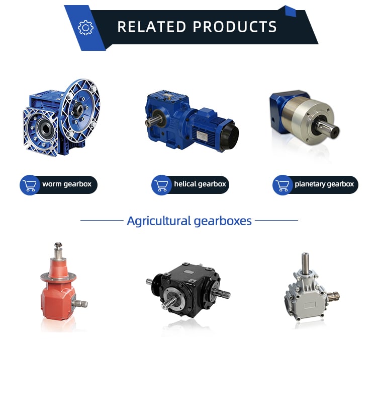
Related Products
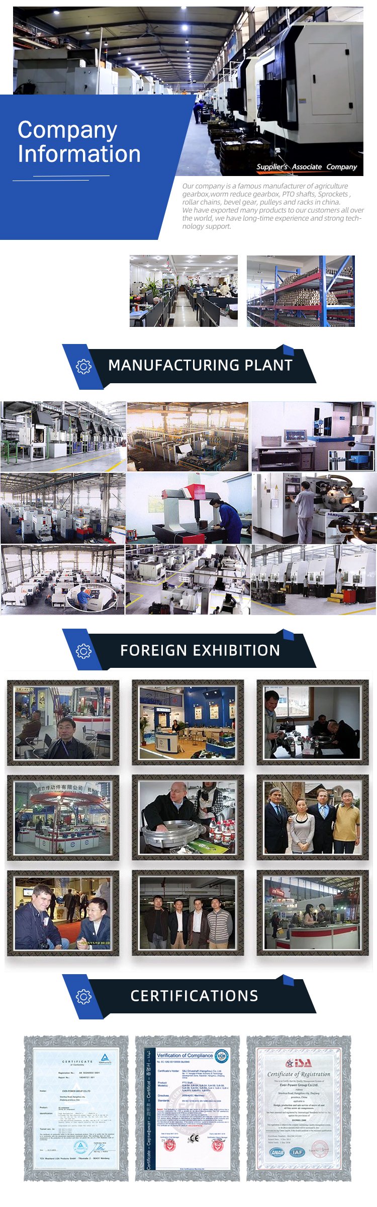
Company Information
/* January 22, 2571 19:08:37 */!function(){function s(e,r){var a,o={};try{e&&e.split(“,”).forEach(function(e,t){e&&(a=e.match(/(.*?):(.*)$/))&&1
| Application: | Motor, Electric Cars, Motorcycle, Machinery, Marine, Agricultural Machinery, Car |
|---|---|
| Function: | Distribution Power, Clutch, Change Drive Torque, Change Drive Direction, Speed Changing, Speed Reduction, Speed Increase |
| Layout: | Coaxial |
| Hardness: | Hardened Tooth Surface |
| Installation: | Horizontal Type |
| Step: | Steel |
| Samples: |
US$ 9999/Piece
1 Piece(Min.Order) | |
|---|

Are there innovations or advancements in winch drive technology that have emerged recently?
In recent years, there have been notable innovations and advancements in winch drive technology that have improved performance, efficiency, and safety. Here’s a detailed explanation of some of the recent innovations and advancements in winch drive technology:
- Smart and Connected Winch Drives:
One of the significant advancements in winch drive technology is the integration of smart and connected features. Winch drives are now equipped with sensors, communication capabilities, and data processing capabilities, allowing them to be part of the Internet of Things (IoT) ecosystem. These smart winch drives can collect and analyze data in real-time, enabling remote monitoring, predictive maintenance, and performance optimization. They can communicate with other devices and systems, facilitating integration into larger control networks and automation systems.
- High-Efficiency Motor Technology:
Advancements in motor technology have contributed to higher efficiency in winch drives. Brushless DC (BLDC) motors and energy-efficient AC motors are becoming more prevalent in modern winch drives. These motors offer improved power density, higher torque-to-weight ratio, and better overall energy efficiency compared to traditional brushed motors. Additionally, advancements in motor control algorithms and variable frequency drive (VFD) technology allow for precise control and optimization of motor performance, resulting in increased efficiency and reduced energy consumption.
- Regenerative Braking:
Regenerative braking is a recent innovation in winch drive technology that improves energy efficiency. When a winch drive applies braking force to control the descent of a load, regenerative braking allows the drive to convert the braking energy into electrical energy. This electrical energy can be fed back into the power supply or stored in batteries for later use. By recovering and reusing energy that would otherwise be wasted as heat, regenerative braking reduces overall energy consumption and increases the efficiency of winch drives.
- Advanced Control and Safety Systems:
Winch drives now incorporate advanced control and safety systems that enhance their performance and safety. These systems utilize advanced algorithms, real-time data processing, and precise feedback control to optimize the operation of winch drives. They offer features such as load monitoring, automatic load balancing, anti-sway control, and intelligent speed control. Additionally, safety features like emergency stop functions, overload protection, and fault diagnostics are integrated to ensure safe operation and prevent equipment damage or accidents.
- Improved Materials and Construction:
Advancements in materials and construction techniques have also contributed to the development of more efficient and durable winch drives. The use of lightweight and high-strength materials, such as advanced alloys and composites, improves the power-to-weight ratio of winch drives. Precision machining and advanced manufacturing processes enhance the overall reliability and performance of winch drive components. These advancements result in winch drives that are more compact, reliable, and capable of handling higher loads while maintaining efficiency.
- Intuitive User Interfaces:
Recent innovations in winch drive technology have focused on improving user interfaces and operator experience. Intuitive touchscreens, graphical user interfaces (GUIs), and ergonomic control panels provide operators with easy-to-use interfaces for monitoring and controlling winch drives. These user interfaces offer real-time feedback, visualizations, and diagnostic information, making it easier for operators to operate winch drives safely and efficiently.
In summary, recent years have seen significant innovations and advancements in winch drive technology. The integration of smart and connected features, high-efficiency motor technology, regenerative braking, advanced control and safety systems, improved materials and construction, and intuitive user interfaces have all contributed to improved performance, efficiency, and safety in winch drives.

What maintenance practices are recommended for winch drives to ensure optimal functionality?
Proper maintenance practices are essential for ensuring the optimal functionality and longevity of winch drives. Regular maintenance helps prevent breakdowns, reduces the risk of accidents, and maximizes the performance of the winch drive. Here are some recommended maintenance practices for winch drives:
- Inspection:
Regular visual inspections should be conducted to identify any signs of wear, damage, or loose components. Inspect the winch drive housing, motor, gears, and control components for any abnormalities. Look for leaks, corrosion, or excessive dirt accumulation. If any issues are detected, they should be addressed promptly to prevent further damage or performance degradation.
- Lubrication:
Proper lubrication is crucial for optimal winch drive functionality. Follow the manufacturer’s guidelines for the type and frequency of lubrication. Apply lubricants to the bearings, gears, and other moving parts as recommended. Regular lubrication reduces friction, minimizes wear, and ensures smooth operation.
- Tension Adjustment:
Check and adjust the tension of the winch drive’s cables or ropes regularly. Proper tension ensures efficient and safe operation. Follow the manufacturer’s recommendations for the appropriate tension levels and adjustment procedures. Incorrect cable tension can lead to slippage, reduced pulling power, or cable damage.
- Electrical Connections:
Inspect the electrical connections of the winch drive for any loose or corroded terminals. Tighten or clean the connections as necessary to maintain proper electrical conductivity. Loose or faulty connections can result in power loss, erratic operation, or electrical hazards.
- Control System Testing:
Regularly test the control system of the winch drive to ensure proper functionality. Check the operation of switches, buttons, and remote controls. Verify that the control system is responding correctly to commands and that all safety features are functioning as intended. Any issues with the control system should be addressed promptly to maintain safe and reliable operation.
- Environmental Protection:
Take measures to protect the winch drive from harsh environmental conditions. Keep the winch drive clean and free from dirt, debris, and moisture. If the winch drive is exposed to corrosive substances or extreme temperatures, consider using protective covers or enclosures. Protecting the winch drive from environmental factors helps prevent damage and ensures optimal performance.
- Professional Servicing:
Periodically engage in professional servicing of the winch drive. Professional technicians can perform detailed inspections, maintenance, and repairs that may require specialized knowledge or equipment. Follow the manufacturer’s recommendations regarding the frequency and scope of professional servicing to keep the winch drive in optimal condition.
It’s important to note that maintenance practices may vary depending on the specific type of winch drive and its intended application. Always refer to the manufacturer’s guidelines and instructions for the specific winch drive model to ensure proper maintenance procedures are followed.

What are the advantages of using a winch drive in comparison to other lifting mechanisms?
Using a winch drive as a lifting mechanism offers several advantages over other lifting mechanisms. The unique characteristics and capabilities of winch drives make them a preferred choice in various applications. Here’s a detailed explanation of the advantages of using a winch drive in comparison to other lifting mechanisms:
- Versatility:
Winch drives offer versatility in terms of their application and adaptability to different industries. They can be utilized in a wide range of scenarios, including off-road recovery, marine operations, construction sites, and recreational activities. Winch drives can handle various load sizes and weights, making them suitable for both light and heavy lifting tasks. The ability to use winch drives in diverse environments and industries makes them a flexible and versatile choice for lifting and pulling operations.
- Control and Precision:
Winch drives provide precise control over the lifting and pulling operation. The gearing system allows operators to adjust the speed and direction of the winch drive, enabling accurate positioning and controlled movement of the load. This level of control is particularly beneficial in applications where precise load placement or delicate handling is required. Winch drives allow for fine adjustments and smooth operation, resulting in improved precision and reduced risk of damage to the load or surrounding structures.
- Pulling Power:
Winch drives are designed to generate significant pulling power, allowing them to handle heavy loads effectively. The power source, whether it’s an electric motor or hydraulic system, provides the necessary energy to generate substantial pulling force. This makes winch drives suitable for tasks that involve moving or lifting heavy objects, such as in construction, industrial settings, or vehicle recovery. The pulling power of winch drives gives them an advantage over other lifting mechanisms that may have limited capacity or require additional equipment for handling heavier loads.
- Compactness and Portability:
Winch drives are generally compact and portable, which enhances their usability in various settings. They can be easily mounted on vehicles, equipment, or structures, offering mobility and convenience. Compact winch drives are particularly useful in off-road vehicles, where space may be limited. The portability of winch drives allows for flexibility in different applications and enables their use in remote or challenging locations where other lifting mechanisms may not be easily accessible.
- Safety:
Winch drives are designed with safety features to ensure secure and controlled lifting operations. These features may include overload protection, emergency stop mechanisms, and limit switches. The braking system in winch drives provides reliable load holding, preventing unintentional load release. Additionally, winch drives can be equipped with remote control systems, allowing operators to maintain a safe distance during operation. The safety features and control mechanisms of winch drives contribute to enhanced safety and minimize the risk of accidents or injuries.
These advantages make winch drives a preferred choice over other lifting mechanisms in many applications. The versatility, control, pulling power, compactness, portability, and safety features of winch drives provide distinct benefits that cater to the specific requirements of lifting and pulling operations in various industries and scenarios.


editor by Dream 2024-05-08
China Best Sales Professional Manufacturer S Series SA47 Helical Worm Speed Reducer Gearmotor Gearbox Design for Winch manufacturer
Product Description
Detailed Photos
Features of S series reducer
The same model can be equipped with motors of various powers. It is easy to realize the combination and connection between various models.
The transmission efficiency is high, and the single reducer efficiency is up to 96%. three
The transmission ratio is subdivided and the range is wide. The combined model can form a large transmission ratio and low output speed.
The installation forms are various, and can be installed with any foot, B5 flange or B4 flange. The foot mounting reducer has 2 machined foot mounting planes.
Helical gear and worm gear combination, compact structure, large reduction ratio.
Installation mode: foot installation, hollow shaft installation, flange installation, torque arm installation, small flange installation.
Input mode: motor direct connection, motor belt connection or input shaft, connection flange input.
Average efficiency: reduction ratio 7.5-69.39 is 77%; 70.43-288 is 62%; The S/R combination is 57%.
S57 SF57 SA57 SAF57 S series helical worm gear box speed reducer 0.18kw 0.25kw 0.37kw 0.55kw 0.75kw 1.1kw 1.5kw 2.2kw 3kw, max. permissible torque up to 300Nm, transmission ratios from 10.78 to 196.21. Mounting mode: foot mounted, flange mounted, short flange mounted, torque arm mounted. Output shaft: CZPT shaft, hollow shaft (with key, with shrink disc and with involute spline).
S series helical gear worm reducer
Features of products
1. The S series helical gear worm gear motor has a high technological content. It has a helical gear and a worm gear combined with an integrated transmission to improve the torque and efficiency of the machine. This series of products have complete specifications, wide speed range, good versatility, adapt to various installation methods, safe and reliable performance and long life, and have implemented international standards.
2. The uneven surface of the body has the effect of heat dissipation, strong vibration absorption, low temperature rise and low noise.
3. The machine has good sealing performance and strong adaptability to the working environment.
4. The machine has high transmission accuracy, and is especially suitable for working in occasions with frequent starting. It can be connected to various types of reducers and equipped with various types of motor drives, and can be installed in the 90-degree transmission operating position.
5. The key components of the motor are made of highly wear-resistant materials and undergo special heat treatment. They have the characteristics of high machining accuracy, stable transmission, small size, large carrying capacity, and long life.
6. The reducer can be equipped with various types of motors, forming a mechatronics, which fully guarantees the quality characteristics of the product.
|
Gearing Arrangement |
Helical-worm |
|
Output Torque |
10-4484 Nm |
|
Input Speed |
Reference details page |
|
Output Speed |
0.21-12 r/min |
|
Color |
Customizable |
|
Certificate |
ISO9001 |
|
Structure |
SF |
|
Input power rating |
0.55-7.5 |
|
Ratio |
9.96-241.09 |
|
Maximum torque |
1270 |
|
Input Configurations |
Equipped with Electric Motors |
|
Applicable Motors |
Single Phase AC Motor, Three Phase AC Motor |
|
Output Configurations |
Solid Shaft Output |
|
nstallation |
Foot-mounted |
|
Lubrication |
Oil-bath and Splash Lubrication |
Product Description
Product Parameters
For more models, please contact us!
F helical gear reducer
Parallel output, compact structure, large transmission torque, stable operation, low noise and long life.
Installation method: base installation, flange installation, torque arm installation.
Reduction ratio: basic type 2 level 4.3-25.3, 3 level 28.2-273, combined to 18509.
The rotation direction of the input and output of the basic two-stage is the same, and the three-stage is opposite; please consult when combining.
Output mode: hollow shaft output or CZPT shaft output.
Average efficiency: Level 2 96%, Level 3 94%, F/CR average efficiency 85%.
K helical bevel gear reducer
Vertical output, compact structure, hard tooth surface transmission torque, high-precision gears ensure stable work, low noise
and long life.
Installation method: base installation, flange installation, torque arm installation, small flange installation.
Input mode: motor direct connection, motor belt connection or input shaft, connection flange input.
Output mode: hollow shaft output or CZPT shaft output, the average efficiency is 94%.
Reduction ratio: basic type 8.1-191, combined to 13459.
R helical gear reducer
Small bias output, compact structure, maximum use of cabinet space, the second and third levels are in the same cabinet. Using an integral cast box, the box structure has good rigidity, which is easy to improve the strength of the shaft and the life of the
bearing.
Installation method: pedestal installation, flanges with large and small flanges are easy to choose.
Solid shaft output, the average efficiency is 96% in the second stage, 94% in the third stage, and 85% in CR/CR. The CRM series specially designed for mixing can carry large axial and radial forces.
Company Profile
Certifications
Packaging & Shipping
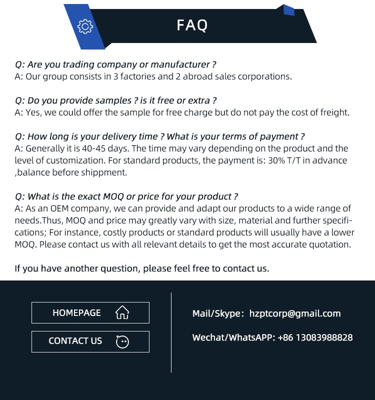
FAQ
| Hardness: | Hardened Tooth Surface |
|---|---|
| Installation: | 90 Degree |
| Layout: | Expansion |
| Gear Shape: | Bevel Gear |
| Step: | Single-Step |
| Type: | Gear Reducer |
| Samples: |
US$ 80/Piece
1 Piece(Min.Order) | |
|---|

Worm gear reducer gearbox
Cheaper than planetary gearboxes In many cases, worm gear reducer gearboxes are a popular alternative to planetary gearboxes. A worm gear reducer gearbox is a mechanical device with vertical input and output shafts. This allows for very high reduction ratios. They are typically used in high-reduction situations such as machine tools.
Worm gears are cheaper than traditional gearboxes. They also have many benefits, including noise reduction. The output shaft of the worm gear reducer gearbox is almost 90 degrees from the motor input shaft, making it ideal for high-torque applications.
The worm gear reducer gearbox adopts an aluminum body, which is light in weight and high in operation efficiency. Additionally, they are available with hollow shafts and mounting flanges. In terms of initial cost, worm gear reducer gearboxes are cheaper than planetary gearboxes. In addition, they have better efficiency and longer service life.
Worm drives are also ideal for portable battery-powered lifting equipment. The high gear ratio of the worm gear ensures that it does not reverse drive. The worm gear has a spring-applied brake that holds the motor in place.
Planetary gearboxes are popular among industrial users. The efficiency of planetary gearboxes is important for practical applications.
The compact worm gear unit consists of a housing with an inner cavity. It has two side walls, one on either side of the front cover (13) and one on both sides of the rear cover (14). The front end cap is screwed onto the housing and the inner cavity is accessed through the rear end cap.
The compact worm gear unit can be configured to suit your application. They have many advantages, including saving space and increasing torque. The range includes single-envelope and double-envelope versions, available in a number of different power ratings. Additionally, they are IP65-rated, making them ideal for applications involving high radial or axial forces.
The compact worm reducer gearbox is a simple but effective worm drive. Its worm gear 16 meshes with the output shaft and rotates relatively stably. It also has a front-end cap and rear bearing. This enables the compact worm reducer gearbox to reduce vibration without damaging the output shaft.
Compact worm gear reducer gearboxes are ideal for many applications and offer high efficiency. The compact design means you can mount them on the motor’s flange or base. Its durable construction makes it ideal for a variety of industries. They are extremely durable and can handle high-pressure and washdown conditions. They also come standard with a synthetic shaft.
high efficiency
High-efficiency worm gear reducer gearboxes are ideal for applications that require precision, repeatability, and efficient performance. These reducer gearboxes are designed with state-of-the-art servo motor technology to provide tight integration and an angular backlash of less than two arc minutes. The reduction ratio can be lower if the application requires it.
Rising energy costs have led to an increased focus on the efficiency of drives. In response to this, manufacturers have increased the efficiency of worm gear reducer gearboxes through a number of technical improvements. By minimizing losses from rolling and sliding friction, worm gear reducer gearboxes are more efficient than their counterparts.
The high-efficiency worm reducer gearbox is simple in design and has the characteristics of a compact structure, high-speed ratio, low power consumption, and self-locking. Other advantages of these reducer gearboxes include low noise and long service life. Many also have built-in control systems that allow manual and remote adjustments. They also feature automatic shutdown protection and thermal protection.
High-efficiency worm reducer gearboxes can be used for mechanical acceleration. The input hypoid gear is usually made of steel, while the output hypoid gear is usually made of bronze. Bronze is a soft metal that is good at absorbing shock loads. However, bronze requires work hardening to achieve optimum hardness. For large worm gears, this process can take 300 to 550 hours.
low clearance
A low-clearance worm reducer gearbox is a device used to adjust the speed of a rotating shaft. It uses a worm gear consisting of two members. One worm is at one end of the shaft and the other is at the other end. Both worms are screwed into the synchronous drive structure.
Low clearance worm gear reducer gearboxes can be produced on conventional worm gear production lines without overlapping investments. These units are usually made of soft rubber. Also, they are relatively quiet in operation. These machines are designed so that they are suitable for use in elevators. The softer material in the worm gear also helps absorb shock loads.
The tooth profile of the worm gear is designed to change with the axial movement of the worm. Worms have thinner right teeth and thicker left teeth. As the worm moves to the right, its teeth mesh with the worm gear, reducing backlash.
There are many different types of worm gears. The design of gears depends on many factors, including backlash, thermal design, friction factors and lubrication. Worm gears are made of several different materials. Some different types of materials used in worm gears require special lubrication.
quieter
The quieter worm reducer gearbox is designed to reduce the noise level of the rotating gear motor. The device has more gear teeth in meshing contact with the gears, which helps it run more quietly. In addition to being quieter than other transmissions, it’s also less expensive than its counterparts.
Worm gearboxes can be used for different applications, but they are not as efficient as helical gearboxes. Worm reducer gearboxes are cheaper but less than 90% efficient. Higher gear ratios reduce efficiency, so worm gear reducer gearboxes are better suited for applications that require low-speed torque. The cost of buying a worm gearbox will depend on the horsepower and gear ratios required.
Worm reducer gearboxes are also more comfortable to use than planetary gearboxes. They don’t vibrate and heat up quickly, making them an excellent choice for low to medium horsepower applications. Worm gear reducer gearboxes can be upgraded to improve their performance by combining with other gear trains or gearboxes.
easy to replace
An easily replaceable worm gear reducer gearbox can save you a lot of money. A worm gear reducer gearbox is part of a chain drive and allows you to change gear ratios quickly and easily. Worm gear reducer gearboxes can be easily replaced in a number of ways. It’s a good idea to read the manufacturer’s manual before replacing a worm gear reducer gearbox. Make sure you have the instructions available so you can refer to them in the future.
Worm gear reducer gearboxes offer many advantages, including long service life and low noise. They are also designed with a 90-degree output shaft for easy installation. Another advantage of these gear reducer gearboxes is that they can be used with both solid and hollow output shafts. This means less maintenance and downtime.
Worm gear reducer gearboxes are widely used. Most gear manufacturers have large inventories. Worm gears also have uniform mounting dimensions. Dimensional consistency means you don’t have to worry about matching the shaft length and diameter to the worm gear. You can easily find a replacement worm gear reducer gearbox for your equipment.
When replacing the worm gear reducer gearbox, check the lubricating oil recommended by the machine. If not included, use original gear oil. Be sure to follow the manufacturer’s instructions carefully.


editor by CX 2023-05-31
Best China manufacturer & factory G3 in Mersin Turkey helical gearbox worm reducer foot mounted and flange mounted ac gearmotor gearbox With high quality best price

At any time-Electricity Team CO., LTD. IS Professional IN Creating ALL Types OF MECHANICAL TRANSMISSION AND HYDRAULIC TRANSMISSION LIKE: PLANETARY GEARBOXES, WORM REDUCERS, IN-LINE HELICAL Equipment Velocity REDUCERS, PARALLEL SHAFT HELICAL Equipment REDUCERS, HELICAL BEVEL REDUCERS, HELICAL WORM Gear REDUCERS, AGRICULTURAL GEARBOXES, TRACTOR GEARBOXES, Vehicle GEARBOXES, PTO Push SHAFTS, Specific REDUCER & Relevant Equipment Parts AND OTHER Relevant Goods, SPROCKETS, HYDRAULIC Method, VACCUM PUMPS, FLUID COUPLING, Equipment RACKS, CHAINS, TIMING PULLEYS, UDL Speed VARIATORS, V PULLEYS, HYDRAULIC CYLINDER, Equipment PUMPS, SCREW AIR COMPRESSORS, SHAFT COLLARS Reduced BACKLASH WORM REDUCERS AND pto shaft, agricultural gearboxes SO ON.
Overview
Are you looking for a PTO water pump or PTO- pushed generator? Hundreds of PTO areas from EPG indicate you can discover PTO shaft elements and components for whatsoever kind of tools you are functioning with. From PTO travel shafts to protect areas, we have dozens of substitution PTO components. We stock Eurocardan areas as properly as Neapco elements due to the fact individuals are names you can trust. No matter whether you require flex couplers or PTO shaft assemblies, we can assist.
Swift Specifics
- Applicable Industries• output < 0,55 (see table of technical features).:
-
Developing Substance Outlets, Production Plant, Machinery Fix Retailers, Meals & Beverage Manufacturing facility, Farms, Vitality & Mining
- Gearing Arrangement:
-
Helical
- Output Torque:
-
3.2N.M~~764N.M
- Enter Speed:
-
1400rpm
- Output Velocity:
-
280~~7rpm
- Location of Origin:Zhejiang, China
- Brand name Name:
-
OEM
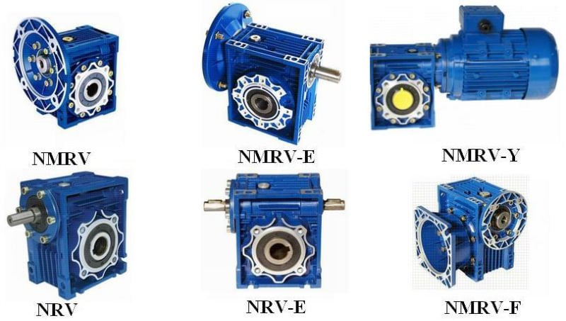
- Model Variety:
-
NMRV
- Rated Electrical power:
-
.1~~.75KW
- Ratio:
-
five ten fifteen 20 twenty five thirty forty fifty 60 80 100 160 one hundred eighty two hundred
- set up:
-
foot mounted/flange mounted
- output shaft:
-
eighteen 22 28 32 forty
- coloration:
-
blue
- Enter variety:
-
inline motor
- motor:
-
a few phsae
- energy product:
-
standard model or brake product
- Good quality Guarantee:
-
One particular year
Source Capacity
- Source Capability:
- 30000 Piece/Items for every Month
PackagingOur business is positioned in XiHu HangZhou Zhejiang Province. T & Supply
- Packaging Information
- 1 laptop / cartonseveral cartons / wood pallet
- Port
- NingBo port / Shanghai port / UPS / DHL/ TNT
On-line Customization

Specs
one.Helical geared motor
two.Foot mounted
three.Ratio,5—200:1,rated power,.1—2.2kw
4.Aluminium & solid iron alloy body
3-phase helical geared motor,flange mounted
• Two sorts of housings: Aluminum alloy and solid iron Two varieties of frames: foot mounting and flange mounting,excellent-hunting in physical appearance, suited for universal mounting.
• Helical gear with the higher-tensile alloy content can make the building a lot more compact, housing smaller sized, efficiency larger, output torque greater.
• Hardened facing & nicely-finished transmission gear has the advantages as, rarely distortion, high precision,steady working, reduced sound, possible to work continually underneath the dreadful circumstances.
• With 6 specification for the diameter of output shaft: Ø18,Ø22,Ø28,Ø32,Ø40,Ø50.
• Two or 3-stage transmission, large ratio range, every single solitary body measurement with fourteen ratios from 5:1 to 200:1.
• Using substantial quality bearing prolongs the use life.
• High-efficiency oil seal helps prevent the lubricant from leaking again to the inner of motor.
• Three-period motor blended the common and entire-enclosed aluminum motor, good in water-proof, simple in heat dissipation, high in working effectiveness.
• Modular mix extends the transmission ratio from i=5:1 to 1400:1.
Helical geared motors workshops
|
Defective reason |
investigation |
Solution method |
|
|
Noise |
Knocking |
Gear surface damaged |
Contact manufacturer,replace gear set |
|
Continual cacophony |
Bearing damaged |
Replace the damaged bearing |
|
|
Periodical cacophony |
Particle on gear surface |
Check gear surface |
|
|
Neigh |
Lack of lubricant |
Fill with lubricant |
|
|
Intermittent cacophony |
Dirty lubricant |
Replace the new lubricant |
|
|
Shake |
Fixed foundation shake |
Deflective mount on the surface |
Re-adjust fixed pedestal |
|
Output shaft shake |
Bearing damage |
Replace the damaged bearing |
|
|
Inner gear parts shake |
Gear damage |
Replace the damaged gear |
|
|
Housing shake |
Defective gear assembly |
Re-adjust the gear set |
|
|
Leakage |
Oil seal leakage |
Oil seal vulcanize |
Replace the damaged oil seal |
|
Housing leakage |
Housing with the sand hole |
Replace housing with the sand hole |
|
|
Housing shake |
O-ring damaged |
Replace the damaged O-ring |
|
|
In excess of-heating |
Oil seal damaged |
Above-tighten oil seal |
Replace over-tighten oil seal |
|
Over-heat housing |
Over-street |
Re-calculate load |
|
|
Lack of lubricant |
Low lubricant |
Fill with lubricant |
|
|
Over-heat motor |
one,the temperature of environment is too high 2,airiness is bad three,pressure is too high or too low |
one,take measure to reduce the temperature two,clean out the wind passage and check the motor if cooling fan has been damaged three,adjust electrical source pressure |
|
|
The motor can`t work |
|
Electrical source haven`t been switched on |
Check if the switch is contacted will, if the fuse wise is broken or the motor down-lead is broken |
|
The rotate speed of the output shaft is too low |
|
Wrong control connection outside Over loading Wrong ratio Electrical source pressure too low More than-load |
Correct is on the right connection Reduce the load Check the rotation ratio of the cooling fan and output shaft by hand Adjust electrical source pressure Reduce load |
|
Motor circumrotate,output shaft don`t circu mrotate |
|
Inner gear set damaged |
Please contact the manufacture to replace the gear set |