Product Description
Why Choose Us
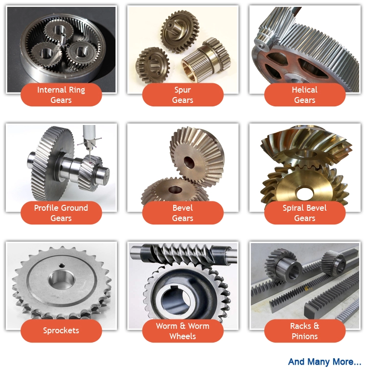
Product Details
|
Type |
Worm Gear Speed Reducer/ gearbox |
|
Model |
WMRV 25/30/40/50/63/75/90/110/130/150/185 |
|
Ratio |
7.5,10,15,20,25,30,40,50,60,80,100. |
|
Color |
Blue(RAL5571)/Silver grey (K9149) Or On Customer Request |
|
Material |
Housing: Aluminum alloy(size 25~90) / Cast iron(size 110~185) |
|
Worm wheel: Aluminum Bronze or Tin Bronze |
|
| Worm shaft: 20CrMn Ti | |
|
Output Shaft: steel-45# |
|
|
Packing |
Carton, Honey Comb Carton, Wooden Case with wooden pallet |
| Warranty | 1 Year |
| Input Power | 0.09kw,0.18kw,1.1KW,1.5KW,2.2KW,3KW,4KW,5.5KW,7.5KW,11Kw and so on. |
| Usages | Industrial Machine: Food Stuff, Ceramics, CHEMICAL, Packing, Dyeing,Wood working, Glass. |
| IEC Flange | IEC standard flange or on customer request |
| Lubricant | Synthetic oil or worm gear oil |
Company Profile
Exhibition
Customized Service
Certificate&Honor
Customer Comments
FAQ
1. How to choose a gearbox which meets our requirement?
You can refer to our catalogue to choose the gearbox or we can help to choose when you provide
the technical information of required output torque, output speed and motor parameter etc.
2. What information shall we give before placing a purchase order?
a) Type of the gearbox, ratio, input and output type, input flange, mounting position, and motor information etc.
b) Housing color.
c) Purchase quantity.
d) Other special requirements.
3. What industries are your gearboxes being used?
Our gearboxes are widely used in the areas of textile, food processing, beverage, chemical industry,
escalator,automatic storage equipment, metallurgy, tabacco, environmental protection, logistics and etc.
4. Do you sell motors?
We have stable motor suppliers who have been cooperating with us for a long-time. They can provide motors
with high quality.
/* January 22, 2571 19:08:37 */!function(){function s(e,r){var a,o={};try{e&&e.split(“,”).forEach(function(e,t){e&&(a=e.match(/(.*?):(.*)$/))&&1
| Application: | Motor, Machinery, Agricultural Machinery |
|---|---|
| Function: | Distribution Power, Speed Changing, Speed Reduction, Speed Increase |
| Layout: | Coaxial |
| Samples: |
US$ 25/Piece
1 Piece(Min.Order) | Order Sample |
|---|
| Customization: |
Available
|
|
|---|
.shipping-cost-tm .tm-status-off{background: none;padding:0;color: #1470cc}
|
Shipping Cost:
Estimated freight per unit. |
about shipping cost and estimated delivery time. |
|---|
| Payment Method: |
|
|---|---|
|
Initial Payment Full Payment |
| Currency: | US$ |
|---|
| Return&refunds: | You can apply for a refund up to 30 days after receipt of the products. |
|---|

Can you explain the impact of winch drives on the overall efficiency of lifting systems?
The efficiency of lifting systems is significantly influenced by the choice and performance of winch drives. Winch drives play a crucial role in converting power into mechanical work to lift or move heavy loads. Here’s a detailed explanation of the impact of winch drives on the overall efficiency of lifting systems:
- Power Transmission:
Winch drives are responsible for transmitting power from the energy source to the lifting mechanism. The efficiency of power transmission directly affects the overall efficiency of the lifting system. Well-designed winch drives minimize power losses due to friction, heat generation, or mechanical inefficiencies. By optimizing the gear system, bearings, and other mechanical components, winch drives can maximize power transmission efficiency and minimize energy waste.
- Mechanical Advantage:
Winch drives provide a mechanical advantage that allows the lifting system to handle heavier loads with less effort. The mechanical advantage is determined by the gear ratio and drum diameter of the winch drive. By selecting an appropriate gear ratio, the winch drive can multiply the input torque, enabling the lifting system to overcome the resistance of the load more efficiently. A higher mechanical advantage reduces the strain on the power source and improves the overall efficiency of the lifting system.
- Speed Control:
Winch drives offer speed control capabilities, allowing operators to adjust the lifting speed according to the specific requirements of the task. The ability to control the lifting speed is essential for efficient and safe operation. By utilizing winch drives with precise speed control mechanisms, the lifting system can optimize the speed to match the load, reducing unnecessary energy consumption and increasing overall efficiency.
- Load Distribution:
Winch drives play a vital role in distributing the load evenly across the lifting system. Uneven load distribution can lead to excessive stress on certain components, reducing the overall efficiency and potentially causing equipment failure. Well-designed winch drives ensure that the load is distributed evenly, minimizing stress concentrations and maximizing the efficiency of the lifting system.
- Control and Safety Features:
Winch drives incorporate control and safety features that contribute to the overall efficiency of the lifting system. Advanced control systems allow for precise positioning and smooth operation, minimizing unnecessary movements and reducing energy consumption. Safety features, such as overload protection or emergency stop mechanisms, help prevent accidents and equipment damage, ensuring uninterrupted and efficient operation of the lifting system.
- Reliability and Maintenance:
The reliability and maintenance requirements of winch drives directly impact the overall efficiency of lifting systems. Well-designed winch drives with robust construction and quality components minimize the risk of breakdowns or unplanned downtime. Additionally, winch drives that are easy to maintain and service reduce the time and resources required for maintenance, maximizing the uptime and efficiency of the lifting system.
In summary, the choice and performance of winch drives have a significant impact on the overall efficiency of lifting systems. By optimizing power transmission, providing a mechanical advantage, offering speed control, ensuring load distribution, incorporating control and safety features, and prioritizing reliability and maintenance, winch drives can enhance the efficiency, productivity, and safety of lifting operations.

How does the design of winch drives impact their performance in different environments?
The design of winch drives plays a critical role in determining their performance in different environments. Various design factors influence the reliability, efficiency, and adaptability of winch drives to specific operating conditions. Here’s a detailed explanation of how the design of winch drives impacts their performance:
- Load Capacity and Power:
The design of winch drives directly affects their load capacity and power capabilities. Factors such as motor size, gear ratio, and drum diameter determine the maximum load capacity a winch drive can handle. The power output of the motor and the mechanical advantage provided by the gear system impact the winch drive’s ability to lift or pull heavy loads effectively. A well-designed winch drive with appropriate load capacity and power ensures optimal performance in different environments.
- Speed and Control:
The design of winch drives influences their speed and control characteristics. The gear ratio and motor specifications determine the speed at which the winch drive can operate. Additionally, the presence of a variable speed control mechanism allows for precise and controlled movement of loads. The design should strike a balance between speed and control, depending on the specific application and operational requirements in different environments.
- Drive System:
Winch drives can utilize different drive systems, such as electric, hydraulic, or pneumatic. The design of the drive system impacts the performance of the winch drive in different environments. Electric winch drives are commonly used due to their ease of use, precise control, and suitability for various applications. Hydraulic winch drives offer high power output and are often preferred in heavy-duty applications. Pneumatic winch drives are suitable for environments where electricity or hydraulics are not readily available. The design should align with the specific requirements and constraints of the environment in which the winch drive will be used.
- Enclosure and Protection:
The design of the winch drive enclosure and protection features significantly impacts its performance in different environments. Winch drives used in outdoor or harsh environments should have robust enclosures that provide protection against dust, moisture, and other contaminants. Sealed or weatherproof enclosures prevent damage to internal components and ensure reliable operation. Additionally, features such as thermal protection and overload protection are designed to safeguard the winch drive from overheating or excessive strain, enhancing its performance and longevity.
- Mounting and Installation:
The design of winch drives should consider the ease of mounting and installation. Mounting options such as bolt-on, weld-on, or integrated mounting plates offer flexibility for different installation scenarios. The design should also take into account the space constraints and mounting requirements of the specific environment. Easy and secure installation ensures proper alignment, stability, and efficient operation of the winch drive.
- Control and Safety Features:
The design of winch drives includes control and safety features that impact their performance in different environments. Control systems can range from simple push-button controls to advanced remote controls or integrated control panels. The design should provide intuitive and user-friendly control interfaces for efficient operation. Safety features such as emergency stop mechanisms, load limiters, and overload protection are crucial to prevent accidents and ensure safe operation in various environments. The design should prioritize the incorporation of appropriate safety features based on the specific application and environmental conditions.
By considering these design factors, winch drives can be optimized for performance, reliability, and safety in different environments. A well-designed winch drive that aligns with the specific requirements of the environment will deliver efficient and effective lifting or pulling capabilities while ensuring long-term durability and functionality.

In what industries or scenarios are winch drives commonly employed?
Winch drives find extensive utilization in various industries and scenarios that require controlled pulling or lifting capabilities. Their versatility and reliability make them valuable tools in a wide range of applications. Here’s a detailed explanation of the industries and scenarios where winch drives are commonly employed:
- Off-Road and Automotive:
Winch drives are widely utilized in off-road vehicles, such as trucks, SUVs, and ATVs, for recovery purposes. They are essential in scenarios where vehicles get stuck or need to be pulled out of challenging terrain. Winch drives mounted on the front or rear bumpers of off-road vehicles provide the necessary pulling power to extricate vehicles from mud, sand, or other obstacles. In the automotive industry, winch drives are also employed in car haulers and trailers for loading and unloading vehicles, as well as in automotive repair and maintenance for tasks like engine removal and frame straightening.
- Marine and Boating:
Winch drives play a crucial role in the marine and boating industry. They are commonly used for anchoring, mooring, and handling heavy loads. Sailboats and powerboats utilize winches to control the sails, raise and lower the anchor, and assist in docking. Larger vessels and ships employ winch drives for cargo handling, launching and recovering small boats or life rafts, and handling equipment on deck. Winch drives in the marine industry offer precise and controlled pulling or lifting capabilities in demanding maritime environments.
- Construction and Industrial:
The construction and industrial sectors heavily rely on winch drives for various tasks requiring the movement of heavy materials and equipment. Winches are commonly used in cranes, hoists, and lifting systems for raising and lowering loads, positioning materials, and erecting structures. They are also found in material handling equipment, such as forklifts and telehandlers, to assist in loading and unloading operations. Winch drives are invaluable in construction sites for activities like tensioning cables, pulling machinery, and operating temporary lifts. Their robustness and reliability make them indispensable tools in the construction and industrial industries.
- Recreational and Adventure:
Winch drives are utilized in various recreational and adventure scenarios to provide controlled movement and enhance safety. In amusement parks and adventure facilities, winches are often used in zip line systems, enabling participants to traverse from one point to another safely. They are also employed in aerial lifts and chairlifts for ski resorts and mountainous areas. Winch drives provide the necessary pulling power and controlled speed, ensuring the safety and enjoyment of individuals engaging in recreational activities. Additionally, winches are utilized in stage productions and theatrical settings to create dynamic effects, such as flying performers or moving set pieces.
- Oil and Gas:
In the oil and gas industry, winch drives are commonly employed in various operations. They are used for tasks such as wireline operations, well intervention, and the handling of heavy equipment. Winch drives assist in lowering and raising tools and instruments into wellbores, as well as in the deployment and retrieval of subsea equipment and structures. They provide the necessary pulling power and control to perform critical operations in the oil and gas exploration and production processes.
These are just a few examples of the industries and scenarios where winch drives are commonly employed. Their versatility, strength, and controllability make them valuable tools in numerous applications, ranging from off-road and automotive to marine and boating, construction and industrial, recreational and adventure, and oil and gas industries.


editor by Dream 2024-04-30
China Electric Motor Gear Speed Reducer Worm Gearbox for Belt Transmission worm gearbox calculation
Product Description
Product Description
Main Resources:
one)housing:aluminium alloy ADC12(measurement 571-090) die solid iron HT200(measurement one hundred ten-a hundred and fifty)
two)Worm:20Cr, ZI Involute profile carbonize&quencher warmth therapy make gear floor hardness up to 56-62 HRC Following precision grinding, carburization layer’s thickness amongst .3-.5mm.
3)Worm Wheel:wearable stannum alloy CuSn10-1
Detailed Photos
Mix Possibilities:
Input:with input shaft, With square flange,With IEC common input flange
Output:with torque arm, output flange, solitary output shaft, double output shaft, plastic cover
Worm reducers are obtainable with diffferent combinations: NMRV+NMRV, NMRV+NRV, NMRV+Personal computer, NMRV+UDL, NMRV+MOTORS
Exploded Look at:
Solution Parameters
| Previous Model |
New Model | Ratio | Center Distance | Energy | Input Dia. | Output Dia. | Output Torque | Weight |
| RV571 | 7.5~100 | 25mm | .06KW~.12KW | Φ9 | Φ11 | 21N.m | .7kgs | |
| RV030 | RW030 | seven.5~a hundred | 30mm | .06KW~.25KW | Φ9(Φ11) | Φ14 | 45N.m | 1.2kgs |
| RV040 | RW040 | 7.5~100 | 40mm | .09KW~.55KW | Φ9(Φ11,Φ14) | Φ18(Φ19) | 84N.m | two.3kgs |
| RV050 | RW050 | 7.5~one hundred | 50mm | .12KW~1.5KW | Φ11(Φ14,Φ19) | Φ25(Φ24) | 160N.m | 3.5kgs |
| RV063 | RW063 | 7.5~one hundred | 63mm | .18KW~2.2KW | Φ14(Φ19,Φ24) | Φ25(Φ28) | 230N.m | six.2kgs |
| RV075 | RW075 | seven.5~one hundred | 75mm | .25KW~4.0KW | Φ14(Φ19,Φ24,Φ28) | Φ28(Φ35) | 410N.m | nine.0kgs |
| RV090 | RW090 | 7.5~one hundred | 90mm | .37KW~4.0KW | Φ19(Φ24,Φ28) | Φ35(Φ38) | 725N.m | 13.0kgs |
| RV110 | RW110 | seven.5~100 | 110mm | .55KW~7.5KW | Φ19(Φ24,Φ28,Φ38) | Φ42 | 1050N.m | 35.0kgs |
| RV130 | RW130 | seven.5~a hundred | 130mm | .75KW~7.5KW | Φ24(Φ28,Φ38) | Φ45 | 1550N.m | forty eight.0kgs |
| RV150 | RW150 | 7.5~100 | 150mm | 2.2KW~15KW | Φ28(Φ38,Φ42) | Φ50 | eighty four.0kgs |
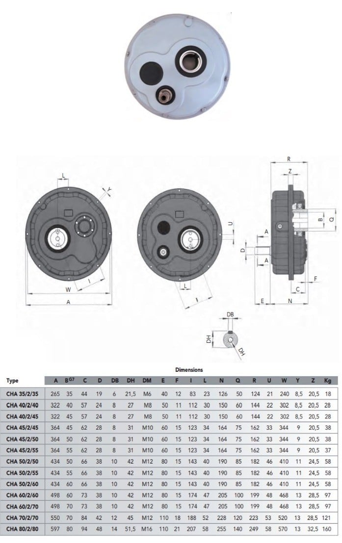
GMRV Define Dimension:
| GMRV | A | B | C | C1 | D(H8) | E(h8) | F | G | G1 | H | H1 | I | M | N | O | P | Q | R | S | T | BL | β | b | t | V |
| 030 | 80 | 97 | fifty four | forty four | 14 | 55 | 32 | 56 | 63 | sixty five | 29 | fifty five | forty | 57 | thirty | 75 | forty four | 6.five | 21 | 5.5 | M6*10(n=4) | 0° | five | 16.three | 27 |
| 040 | a hundred | 121.5 | 70 | 60 | 18(19) | sixty | 43 | 71 | seventy eight | seventy five | 36.5 | 70 | 50 | seventy one.five | forty | 87 | 55 | six.five | 26 | 6.five | M6*10(n=4) | 45° | six | 20.8(21.8) | 35 |
| 050 | a hundred and twenty | 144 | 80 | 70 | 25(24) | 70 | forty nine | 85 | 92 | eighty five | forty three.five | 80 | sixty | 84 | 50 | a hundred | 64 | 8.five | 30 | 7 | M8*twelve(n=4) | 45° | eight | 28.3(27.3) | 40 |
| 063 | a hundred and forty four | 174 | a hundred | 85 | twenty five(28) | 80 | sixty seven | 103 | 112 | ninety five | 53 | 95 | seventy two | 102 | 63 | a hundred and ten | 80 | 8.five | 36 | eight | M8*12(n=8) | 45° | 8 | 28.3(31.3) | 50 |
| 075 | 172 | 205 | a hundred and twenty | 90 | 28(35) | ninety five | seventy two | 112 | a hundred and twenty | a hundred and fifteen | 57 | 112.5 | 86 | 119 | 75 | one hundred forty | ninety three | 11 | forty | ten | M8*14(n=8) | 45° | eight(ten) | 31.3(38.3) | 60 |
| 090 | 206 | 238 | a hundred and forty | a hundred | 35(38) | one hundred ten | seventy four | a hundred thirty | one hundred forty | one hundred thirty | sixty seven | 129.5 | 103 | 135 | 90 | 160 | 102 | thirteen | 45 | eleven | M10*sixteen(n=8) | 45° | 10 | 38.3(forty one.3) | 70 |
| one hundred ten | 255 | 295 | a hundred and seventy | a hundred and fifteen | 42 | a hundred thirty | – | one hundred forty four | 155 | 165 | 74 | a hundred and sixty | 127.5 | 167.5 | a hundred and ten | 200 | a hundred twenty five | fourteen | 50 | 14 | M10*18(n=8) | 45° | twelve | 45.three | 85 |
| 130 | 293 | 335 | two hundred | 120 | forty five | one hundred eighty | – | one hundred fifty five | one hundred seventy | 215 | 81 | 179 | 146.5 | 187.5 | a hundred thirty | 250 | 140 | 16 | 60 | 15 | M12*20(n=8) | 45° | 14 | forty eight.8 | a hundred |
| 150 | 340 | four hundred | 240 | 145 | 50 | a hundred and eighty | – | 185 | 200 | 215 | ninety six | 210 | 170 | 230 | a hundred and fifty | 250 | one hundred eighty | 18 | 72.5 | eighteen | M12*22(n=8) | 45° | 14 | fifty three.eight | 120 |
Organization Profile
About CZPT Transmission:
We are a professional reducer producer situated in HangZhou, ZHangZhoug province.
Our leading goods is full range of RV571-one hundred fifty worm reducers , also equipped GKM hypoid helical gearbox, GRC inline helical gearbox, Laptop models, UDL Variators and AC Motors, G3 helical gear motor.
Items are broadly used for programs these kinds of as: foodstuffs, ceramics, packing, chemical compounds, pharmacy, plastics, paper-producing, construction machinery, metallurgic mine, environmental defense engineering, and all sorts of automatic strains, and assembly lines.
With quick supply, outstanding soon after-sales provider, innovative generating facility, our items market well both at residence and overseas. We have exported our reducers to Southeast Asia, Eastern Europe and Middle East and so on.Our purpose is to create and innovate on basis of high high quality, and develop a good track record for reducers.
Packing data:Plastic Baggage+Cartons+Wooden Instances , or on ask for
We take part Germany Hannver Exhibition-ZheJiang PTC Fair-Turkey Earn Eurasia
Logistics
Right after Sales Support
1.Upkeep Time and Guarantee:Inside 1 calendar year soon after receiving goods.
2.Other Provider: Such as modeling assortment guidebook, set up manual, and issue resolution information, etc.
FAQ
1.Q:Can you make as for each client drawing?
A: Sure, we supply personalized support for customers appropriately. We can use customer’s nameplate for gearboxes.
2.Q:What is your phrases of payment ?
A: thirty% deposit prior to production,equilibrium T/T just before supply.
3.Q:Are you a trading business or maker?
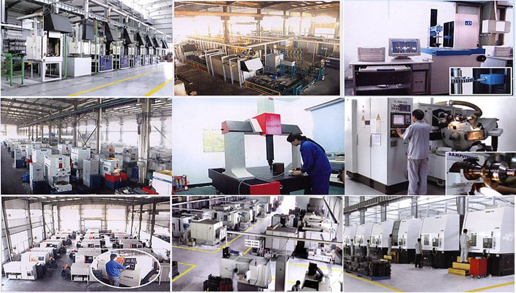
A:We are a manufacurer with sophisticated equipment and experienced workers.
four.Q:What’s your generation capability?
A:8000-9000 PCS/Month
5.Q:Cost-free sample is obtainable or not?
A:Indeed, we can offer cost-free sample if buyer concur to pay out for the courier expense
6.Q:Do you have any certificate?
A:Indeed, we have CE certification and SGS certificate report.
Make contact with information:
Ms Lingel Pan
For any questions just come to feel cost-free ton contact me. Numerous many thanks for your variety consideration to our organization!
|
/ Piece | |
1 Piece (Min. Order) |
###
| Application: | Motor, Machinery, Marine, Agricultural Machinery, Industry |
|---|---|
| Hardness: | Hardened Tooth Surface |
| Installation: | Horizontal Type |
| Layout: | Right Angle |
| Gear Shape: | Worm Gear |
| Step: | Double-Step |
###
| Samples: |
US$ 12/Piece
1 Piece(Min.Order) |
|---|
###
| Customization: |
|---|
###
| Old Model |
New Model | Ratio | Center Distance | Power | Input Dia. | Output Dia. | Output Torque | Weight |
| RV025 | 7.5~100 | 25mm | 0.06KW~0.12KW | Φ9 | Φ11 | 21N.m | 0.7kgs | |
| RV030 | RW030 | 7.5~100 | 30mm | 0.06KW~0.25KW | Φ9(Φ11) | Φ14 | 45N.m | 1.2kgs |
| RV040 | RW040 | 7.5~100 | 40mm | 0.09KW~0.55KW | Φ9(Φ11,Φ14) | Φ18(Φ19) | 84N.m | 2.3kgs |
| RV050 | RW050 | 7.5~100 | 50mm | 0.12KW~1.5KW | Φ11(Φ14,Φ19) | Φ25(Φ24) | 160N.m | 3.5kgs |
| RV063 | RW063 | 7.5~100 | 63mm | 0.18KW~2.2KW | Φ14(Φ19,Φ24) | Φ25(Φ28) | 230N.m | 6.2kgs |
| RV075 | RW075 | 7.5~100 | 75mm | 0.25KW~4.0KW | Φ14(Φ19,Φ24,Φ28) | Φ28(Φ35) | 410N.m | 9.0kgs |
| RV090 | RW090 | 7.5~100 | 90mm | 0.37KW~4.0KW | Φ19(Φ24,Φ28) | Φ35(Φ38) | 725N.m | 13.0kgs |
| RV110 | RW110 | 7.5~100 | 110mm | 0.55KW~7.5KW | Φ19(Φ24,Φ28,Φ38) | Φ42 | 1050N.m | 35.0kgs |
| RV130 | RW130 | 7.5~100 | 130mm | 0.75KW~7.5KW | Φ24(Φ28,Φ38) | Φ45 | 1550N.m | 48.0kgs |
| RV150 | RW150 | 7.5~100 | 150mm | 2.2KW~15KW | Φ28(Φ38,Φ42) | Φ50 | 84.0kgs |
###
| GMRV | A | B | C | C1 | D(H8) | E(h8) | F | G | G1 | H | H1 | I | M | N | O | P | Q | R | S | T | BL | β | b | t | V |
| 030 | 80 | 97 | 54 | 44 | 14 | 55 | 32 | 56 | 63 | 65 | 29 | 55 | 40 | 57 | 30 | 75 | 44 | 6.5 | 21 | 5.5 | M6*10(n=4) | 0° | 5 | 16.3 | 27 |
| 040 | 100 | 121.5 | 70 | 60 | 18(19) | 60 | 43 | 71 | 78 | 75 | 36.5 | 70 | 50 | 71.5 | 40 | 87 | 55 | 6.5 | 26 | 6.5 | M6*10(n=4) | 45° | 6 | 20.8(21.8) | 35 |
| 050 | 120 | 144 | 80 | 70 | 25(24) | 70 | 49 | 85 | 92 | 85 | 43.5 | 80 | 60 | 84 | 50 | 100 | 64 | 8.5 | 30 | 7 | M8*12(n=4) | 45° | 8 | 28.3(27.3) | 40 |
| 063 | 144 | 174 | 100 | 85 | 25(28) | 80 | 67 | 103 | 112 | 95 | 53 | 95 | 72 | 102 | 63 | 110 | 80 | 8.5 | 36 | 8 | M8*12(n=8) | 45° | 8 | 28.3(31.3) | 50 |
| 075 | 172 | 205 | 120 | 90 | 28(35) | 95 | 72 | 112 | 120 | 115 | 57 | 112.5 | 86 | 119 | 75 | 140 | 93 | 11 | 40 | 10 | M8*14(n=8) | 45° | 8(10) | 31.3(38.3) | 60 |
| 090 | 206 | 238 | 140 | 100 | 35(38) | 110 | 74 | 130 | 140 | 130 | 67 | 129.5 | 103 | 135 | 90 | 160 | 102 | 13 | 45 | 11 | M10*16(n=8) | 45° | 10 | 38.3(41.3) | 70 |
| 110 | 255 | 295 | 170 | 115 | 42 | 130 | – | 144 | 155 | 165 | 74 | 160 | 127.5 | 167.5 | 110 | 200 | 125 | 14 | 50 | 14 | M10*18(n=8) | 45° | 12 | 45.3 | 85 |
| 130 | 293 | 335 | 200 | 120 | 45 | 180 | – | 155 | 170 | 215 | 81 | 179 | 146.5 | 187.5 | 130 | 250 | 140 | 16 | 60 | 15 | M12*20(n=8) | 45° | 14 | 48.8 | 100 |
| 150 | 340 | 400 | 240 | 145 | 50 | 180 | – | 185 | 200 | 215 | 96 | 210 | 170 | 230 | 150 | 250 | 180 | 18 | 72.5 | 18 | M12*22(n=8) | 45° | 14 | 53.8 | 120 |
Worm reducer gearbox
Worm reducer gearboxes are commonly used to reduce the Agknx produced by a rotating shaft. They can achieve reduction ratios of five to sixty. In contrast, a single-stage hypoid gear can achieve up to a 120:1 reduction ratio. For further reduction, another type of gearing is used. So, a single stage worm reducer gearbox cannot achieve higher ratios than these.<br
Mechanics
A worm reducer gearbox is an auxiliary mechanical device that uses worms to reduce the size of a rotating shaft. These worms have a range of tooth forms. One form is a line weave twist surface. Another is a trapezoid based on a central cross section. The trapezoid can be perpendicular to the tooth cross section, or it can be normal to the root cross section. Other forms include involute helicoids and convolute worms, which use a straight line intersecting the involute generating line.
Worm gears are lubricated with a special lubricant. Because worm gears are complex, it’s important to use the correct lubricant. Worm gear manufacturers provide approved lubricants for their gears. Using unapproved gear oil can damage your reducer gearbox’s efficiency. The right lubricant depends on several factors, including load, speed, duty cycle, and expected operating temperatures.
The efficiency of a worm gear reducer gearbox depends on several factors, including losses at gear mesh, losses in the bearings, and windage in the oil seal lip. In addition, the worm gear reducer gearbox’s efficiency varies with ambient temperature and operating temperature. The worm gear reducer gearbox’s efficiency can also vary with the ratio of the load. Moreover, worm gear reducer gearboxes are subject to break-in.
Worm gear reducer gearboxes are used in many different applications. They are typically used in small electric motors, but they’re also used in conveyor systems, presses, elevators, and mining applications. Worm gears are also commonly found in stringed musical instruments.
Worm gears have excellent reduction ratios and high Agknx multiplication, and they’re often used as speed reducer gearboxes in low to medium-speed applications. However, the efficiency of worm gear reducer gearboxes decreases with increasing ratios.
Sizes
Worm reducer gearboxes come in different sizes and tooth shapes. While the tooth shape of one worm is similar to the other, different worms are designed to carry a different amount of load. For example, a circular arc worm may have a different tooth shape than one with a secondary curve. Worm gears can also be adjusted for backlash. The backlash is the difference between the advancing and receding arc.
There are two sizes of worm reducer gearboxes available from Agknx Transmission. The SW-1 and SW-5 models offer ratios of 3.5:1 to 60:1 and 5:1 to 100:1 respectively. The size of the worm reducer gearbox is determined by the required gear ratio.
Worm gears have different thread counts. One is based on the central cross-section of the worm, and the other is on the right. Worm gears can have either a single or double thread. Single-threaded gears will reduce speed by 50 percent, while double-threaded gears will reduce speed by 25 percent.
Worm gear reducer gearboxes are lightweight and highly reliable. They can accommodate a variety of NEMA input flanges and hollow output bore sizes. Worm reducer gearboxes can be found at 6 regional warehouses, with prepaid freight. To make a purchasing decision, you should consider the horsepower and Agknx requirements of your specific application.
Applications
The Worm reducer gearbox market is a global business that is dominated by the North American and European regions. The report provides in-depth information on the market trends, key challenges, and opportunities. It also examines the current state of the industry and projects future market growth. The report is organized into segments based on product type, major geographical regions, and application. It also presents statistics and key data about the market.
Worm gear reducer gearboxes have many applications. They can be used to increase the speed of convey belts. They also help reduce noise. Worm gears have many teeth that touch the gear mesh, which makes them quieter. Moreover, the worm gears require only a single stage reducer gearbox, reducing the number of moving parts in the system.
The worm gear has long life and is suitable for different industries. It is a perfect choice for elevators and other applications that need fast stopping and braking. Its compact size and ability to hold a load make it suitable for these applications. It also prevents the load from free-falling as a result of a sudden braking. Worm gears can also be used in heavy-duty machinery such as rock crushers.
Worm gears are similar to ordinary gears except that they transfer motion at a 90-degree angle. As a result, the worm gears are extremely quiet, making them a suitable option for noise sensitive applications. They are also excellent for low-voltage applications, where the noise is critical.
Worm gears are ideal for applications with space restrictions, because they require fewer gear sets. The worm gears also allow for a smaller gearbox size. Consequently, they are the perfect choice for machines that are space-constrained, such as conveyors and packaging equipment.
Cost
The lifespan of a worm gear reducer gearbox is comparable to other gear reducer gearboxes. Worm gears have a long history of innovation and use in various industries, from shipbuilding to automobile manufacturing. Today, these gear reducer gearboxes are still popular with engineers. However, there are some things to keep in mind before buying one.
In the first place, a worm reducer gearbox needs to be affordable. Generally, a worm reducer gearbox costs about $120. The price varies with the brand name and features. Some products are more expensive than others, so be sure to shop around for the best price. In addition, it is important to consider the quality and design of the worm reducer gearbox before making a purchase.
Worm gear manufacturers have made significant advancements in materials, design and manufacturing. These advancements, along with the use of advanced lubricants, have resulted in significant increases in efficiency. For example, double enveloping worm gear reducer gearboxes have improved efficiency by three to eight percentage points. This improvement was achieved through rigorous testing of manufacturing processes and materials. With these improvements, worm gear reducer gearboxes have become more desirable in today’s market.
Worm reducer gearboxes are extremely versatile and reliable, and are available in a variety of sizes. Domestic manufacturers usually stock a large selection of reducer gearboxes, and are often able to ship them the same day you place your order. Most major domestic worm gear reducer gearbox manufacturers also share some critical mounting dimensions, such as the output shaft diameter, the mounting hole location, and the overall reducer gearbox housing height. Most manufacturers also offer standardized gear ratios. Some manufacturers have also improved gear design and added synthetic lubricants for better performance.
In addition, different tooth shapes of worms can increase their load carrying capacity. They can be used on secondary curves and circular arc cross sections. Moreover, the pitch point defines the boundary of the cross section. The mesh on the receding arc is smoother than that of the advancing arc. However, in the case of negative shifting, most of the mesh is on the receding arc.
Self-locking function
A worm reducer gearbox has a self-locking function. When a worm is fitted with all of its addendum teeth, the total number of teeth in the system should be greater than 40. This self-locking function is achieved through the worm’s rack and pinion mechanism. The worm’s self-locking feature can prevent the load from being dropped and is useful for many applications.
The self-locking function of a worm reducer gearbox is possible for two main reasons. First of all, a worm reducer gearbox uses two or more gears. One gear is placed at the input, and the other gear runs the output shaft. This mechanism produces a torque, which is transmitted to a spur gear.
Worm reducer gearboxes can be used in a variety of industrial applications. Because of their self-locking function, they are useful for preventing back-driving. They are also helpful for lifting and holding loads. Their self-locking mechanism allows for a large gear reduction ratio without increasing the size of a gear box.
Self-locking gears can be used to prevent back-driving and inertial driving. This is useful for many industries and can prevent backdriving. However, one major disadvantage of self-locking gears is their sensitivity to operating conditions. Lubrication, vibration, and misalignment can affect their reliability.
Embodiments of the invention provide a self-locking mechanism that prevents back-driving but allows forward-driving. The self-locking mechanism may comprise first and second ratchet cams disposed about a gear member. A releasable coupling member may be interposed between the gear member and the ratchet cam. This facilitates selective coupling and decoupling.
The worm reducer gearbox has several advantages. Its compact design is ideal for many mechanical transmission systems. It also provides greater load capacity than a cross-axis helical gear mechanism.


editor by CX 2023-04-14
Best China manufacturer & factory china in Panama City Panama supplier Chinese helical bevel speed reducer with electric reduction gear motor reductor for conveyor With high quality best price

Our organization pays specific consideration to customers’ needs, listening to the specific requirements of every consumer and guaranteeing complete gratification.
Overview
Swift Information
- Applicable Industries:
-
Manufacturing Plant
- Pole:
-
A single/Two/3 Stage Velocity Reducer
- Ratio:
-
11-87
- Housing Material:
-
Solid Iron
- Working temperature:
-
-40~45℃
- Software:
-
mining, chemical sector,steel metallurgy,lifting transpor and ect.
- Approach:
-
Carburizing, Nitriding , Grinding
- Efficiency:
-
ninety four%~98%
- Mounting Situation:
-
Horizontal,Vertical,Flange
- Colour:
-
Blue,Inexperienced,Gray,Crimson
- Kind:
-
helical bevel with electric powered reduction equipment motor reductor for conveyor
Packaging & Delivery
-
Lead Time
: -
Quantity(Bags) one – 20 >20 Est. Time(days) fifteen To be negotiated
On the web Customization
Product Description

R series Helical Equipment Motor Reducer
Challenging Tooth Sureface Gear EPG——industrial gearbox producers
Chinese electric motor velocity reducer is broadly utilised in mining machinery, chemical sector,metal metallurgy, gentle industry,environmental security, paper producing, printing, lifting transport, food business and so on.
Main Series PrCustomer Help EPG is fully commited to providing world class buyer assist, for equally existing and legacy items, putting you, our buyer, at the heart of everything we do, we actually are with you at every change.oduct: R collection helical gear reducer, K series spiral bevel gear reducer, NGW, P collection planetary reducer, H B series gearbox, Z (ZDY, ZLY, ZSY, and ZFY) serial hard tooth surface cylindrical equipment reducer, D (DBY and DCY) serial hard tooth surface cone equipment reducer, cycloid reducer, etc. In the meantime, map sample processing organization can be carried out.
Made on the foundation of modular blended technique,
the gear reducer have ample mixtures of motor,mounting position and composition projects,
the classifying class of transmission ratio is thorough,
which is suitable for distinct doing work situation and comprehend mechatronics.
Attribute:
-
Applicable to the metallurgical,electrical power technology,drinking water treatment method,development,chemical,paper,
textiles,drugs,meals and other industries.
-
The transmission effectiveness of solitary-stage can attain up to 98%, two-stage can attain 96%, three-phase can get to 94%.
-
The equipment processed by Carburizing & Grinding with higher precision.
-
Higher precision equipment, constant transmission, huge load capacity
-
Extended services lifestyle.
- One particular Two 3 Stage Pace ReducWe made, specifically for our buyers, a protecting cone which is flexible and enables less complicated dealing with whilst coupling the PTO on the tractor or working machine. The versatile cone delivers added comfort and ease when coupling the PTO, due to the fact you can get a excellent grip in the limited shaft area.er

Specification
| R Series Specification | |||||||||||||
| Measurement | 17 | 27 | 37 | 47 | fifty seven | sixty seven | 77 | 87 | ninety seven | 107 | 137 | 147 | 167 |
| Construction | R RF | ||||||||||||
| Input power ranking(kw) |
.18-.75 | .eighteen-3. | .18-3. | .eighteen-5.5 | .18-7.5 | .eighteen-7.5 | .eighteen-eleven | .fifty five-22 | .fifty five-30 | 2.2-45 | 5.5-fifty five | 11-90 | 11-160 |
| Ratio | 3.eighty three-74.eighty four | three.37-135.09 | three.33-134.82 | 3.eighty three-176.88 | four.39-186.89 | 4.29-199.eighty one | five.21-195.24 | 5.36-246.fifty four | four.49-289.seventy four | five.06-249.16 | 5.fifteen-222.60 | 5.00-163.31 | ten.24-229.seventy one |
| Permissible torque N.m |
eighty five | one hundred thirty | 200 | 300 | 450 | 600 | 820 | 1550 | 3000 | 4300 | 8000 | 1300 | 18000 |
| Dimensions | 37 | fifty seven | 67 | 77 | 87 | ninety seven | 107 | 127 | 157 |
| Structure | RX RXF | ||||||||
| Input power rating(kw) |
.eighteen-1.1 | .eighteen-5.5 | .eighteen-7.5 | 1.1-eleven | 3-22 | five.5-thirty | 7.5-forty five | seven.5-90 | 11-132 |
| Ratio | one.62-4.43 | 1.3-5.5 | 1.4-6.07 | 1.42-8.00 | one.39-8.sixty five | 1.42-8.23 | one.44-6.sixty three | 5.36-246.fifty four | four.49-289.seventy four |
| Permissible torque N.m |
85 | a hundred thirty | two hundred | 300 | 450 | 600 | 820 | 1550 | 3000 |
Model assortment:
Closely using the best reduction ratio.
Reduction ratio = servo motor speed / reducer output shaft pace
Torque calculation: Torque calculation is quite critical for the lifestyle of reducer, and pay attention to whether or not the optimum torque value (TP) of acceleration exceeds the maximum load torque of the reducer.
The applicable energy is normally the applicable energy of the servo designs on the marketplace, the applicability of the reducer is quite substantial, the functioning coefficient can be preserved over 1.2, but the decision can also be primarily based on their own requirements to determine.Chinese helical bevel velocity reducer with electric reduction gear motor reductor for conveyor.
Gear Reducer is a mechanical transmission in many fields of the national financial system. The merchandise groups lined by the industry incorporate all sorts of gear reducer, planetary equipment reducer and worm gearbox, as effectively as a variety of specific transmission gadgets these kinds of as velocity escalating system, speed management Devices, like a variety of kinds of adaptable transmission units, this sort of as compound transmission. Merchandise and solutions in the field of metallurgy, nonferrous metals, coal, developing components, ships, h2o conservancy, electricity, construction machinerOur merchandise is well-liked exported to the United States, Germany, Australia, Russia, Spain, Hungary, Zimbabwe, Ukraine, Nigeria, Peru, Brazil, Center and South America, Thailand, Pakistan, Indonesia, far more than 60 nations and locations.y and petrochemical industries.
In all fields of countrywide economy and nationwide protection industry, gearbox items have a vast range of applications. Meals light market, electrical equipment, development equipment, metallurgy machinery, cement equipment, environmental protection machinery, electronic appliances, road building equipment, h2o conservancy machinery, chemical machinery, mining equipment, conveyor equipment, creating supplies machinery, rubber equipment, petroleum equipment and other industries have robust need of Reducer products.Chinese helical bevel speed reducer with electrical reduction gear motor reductor for conveyor.
Technologies
Packaging & Shipping and delivery
Company Details
Founded in 1995, HangZhou Ever-Electrical power Power machinery Co.,Ltd has 22 several years of reducer manufacturing experience and reliability. The company has professional engineer crew, sophisticated technological innovation production and competent employees, with located in HangZhou of ZheJiang province which has reliable industrial base and created transportation.
FAQ
1.Q:Are you the manufacturing unit or investing business?
A:We are the skilled Factory with 22 many years of knowledge.
2.Q:Can you customise according to our demands?
A:Of course, we can design nonstandard goods in accordance to customer’s drawing and sample.
3.Q:How extended is the supply date?
A:10-20 operating times.
4.Q:Where is your manufacturing facility?
A:We are in HangZhou of ZheJiang Province, you can get here by substantial velocity train or fly to Jinan.
Welcome to go to us!