Product Description
|
item |
value |
|
Warranty |
1 year |
|
Applicable Industries |
Manufacturing Plant, Construction works , Energy & Mining, Other |
|
Customized support |
OEM |
|
Gearing Arrangement |
Worm |
|
Output Torque |
2.6NM-1195NM |
|
Place of CHINAMFG |
ZheJiang , China |
|
Input speed |
500-1800rpm |
|
Output speed |
10-300rpm |
|
Speed ratio |
7.5,10,15,20,25,30,40,50,60,80,100 |
|
housing material |
Aluminum or cast iron |
| Output shaft diameter | 14-50mm |
|
MOQ |
10pcs |
|
Color |
Customization |
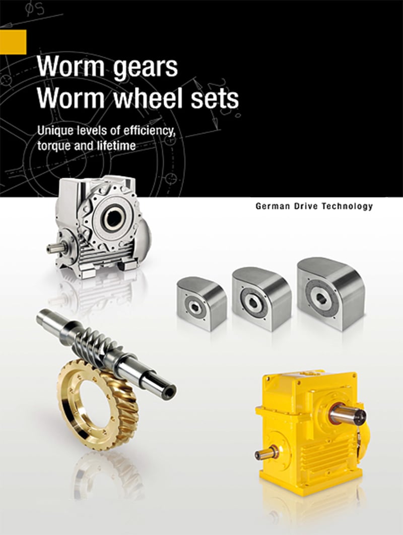
PRODUCTS CHARACTERISTICS
1. Mad of high-quality aluminum alloy,light weight and non-rusting
2. Large output torque
3. Smooth in running and low in noise,can work long time in dreadful conditions.
4. High in radiating efficiency.
5. Good-looking in appearance,durable in service life and small in volume.
6. Suitable for omnibearing installation.
FAQ
Q1:Are you a manufacturer or trading company?
Yes, We are a leading manufacturer specialized in production of various kinds of small and medium-sized
motor.
Q2:How to choose a gearbox which meets our requirement?
You can refer to our catalogue to choose the gearbox or we can help to choose when you provide
the technical information of required output torque, output speed and motor parameter etc.
Q3:What information shall we give before placing a purchase order?
a) Type of the gearbox, ratio, input and output type, input flange, mounting position, and motor information etc.
b) Housing color.
c) Purchase quantity.
d) Other special requirements.
Q4:What industries are your gearboxes being used?
Our gearboxes are widely used in the areas of textile, food processing, beverage, chemical industry, escalator,automatic storage equipment, metallurgy, tabacco, environmental protection, logistics and etc.
Q5:How about your delivery time?
For micro brush dc gear motor, the sample delivery time is 2-5 days, bulk delivery time is about 15-20 days, depends on the order qty. For brushless dc motor, the sample deliver time is about 10-15 days; bulk time is 15-20 days.Please take the sales confirmation for final reference.
Q6:What’s your warranty terms?
One year
/* January 22, 2571 19:08:37 */!function(){function s(e,r){var a,o={};try{e&&e.split(“,”).forEach(function(e,t){e&&(a=e.match(/(.*?):(.*)$/))&&1
| Application: | Motor, Electric Cars, Motorcycle, Machinery, Marine, Agricultural Machinery, Car |
|---|---|
| Function: | Distribution Power, Clutch, Change Drive Torque, Change Drive Direction, Speed Changing, Speed Reduction, Speed Increase |
| Layout: | as for Request |
| Hardness: | Hardened Tooth Surface |
| Installation: | as for Request |
| Step: | as for Request |
| Samples: |
US$ 40/Piece
1 Piece(Min.Order) | |
|---|
| Customization: |
Available
|
|
|---|

How do electronic or computer-controlled components integrate with winch drives in modern applications?
In modern applications, electronic or computer-controlled components play a crucial role in enhancing the functionality, precision, and safety of winch drives. These components integrate with winch drives to provide advanced control, monitoring, and automation capabilities. Here’s a detailed explanation of how electronic or computer-controlled components integrate with winch drives in modern applications:
- Control Systems:
Electronic or computer-controlled components are used to create sophisticated control systems for winch drives. These control systems allow operators to precisely control the speed, direction, and position of the winch drive. By integrating sensors, actuators, and feedback mechanisms, the control system can monitor the operating conditions and adjust parameters in real-time to optimize performance. Control systems may include programmable logic controllers (PLCs), microcontrollers, or dedicated electronic control units (ECUs) that communicate with the winch drive to execute commands and maintain desired operating parameters.
- Human-Machine Interfaces (HMIs):
Electronic components enable the integration of intuitive and user-friendly Human-Machine Interfaces (HMIs) with winch drives. HMIs provide a visual interface for operators to interact with the winch drive system. Touchscreen displays, buttons, switches, and graphical user interfaces (GUIs) allow operators to input commands, monitor system status, and access diagnostic information. HMIs also facilitate the adjustment of control parameters, alarm settings, and operational modes. The integration of HMIs enhances operator control and simplifies the operation of winch drives in modern applications.
- Sensors and Feedback Systems:
Electronic sensors are employed to gather real-time data about various parameters related to the winch drive and the operating environment. These sensors can measure variables such as load weight, cable tension, speed, temperature, and motor current. The collected data is then fed back to the control system, allowing it to make informed decisions and adjustments. For example, if the load exceeds a predefined limit, the control system can send a signal to stop the winch drive or activate an alarm. Sensors and feedback systems ensure accurate monitoring of operating conditions and enable proactive control and safety measures.
- Communication Protocols:
Electronic or computer-controlled components facilitate communication between winch drives and other devices or systems. Modern winch drives often support various communication protocols, such as Ethernet, CAN bus, Modbus, or Profibus, which enable seamless integration with higher-level control systems, supervisory systems, or industrial networks. This integration allows for centralized control, remote monitoring, and data exchange between the winch drive and other components or systems, enhancing coordination and automation in complex applications.
- Automation and Programmability:
Electronic or computer-controlled components enable advanced automation and programmability features in winch drives. With the integration of programmable logic controllers (PLCs) or microcontrollers, winch drives can execute pre-programmed sequences of operations, follow specific load profiles, or respond to external commands and triggers. Automation reduces manual intervention, improves efficiency, and enables synchronized operation with other equipment or systems. Programmability allows customization and adaptation of winch drive behavior to meet specific application requirements.
- Diagnostics and Condition Monitoring:
Electronic components enable comprehensive diagnostics and condition monitoring of winch drives. Built-in sensors, data logging capabilities, and advanced algorithms can monitor the health, performance, and operating parameters of the winch drive in real-time. This information can be used for predictive maintenance, early fault detection, and performance optimization. Additionally, remote access and network connectivity enable remote monitoring and troubleshooting, reducing downtime and improving maintenance efficiency.
In summary, electronic or computer-controlled components integrate with winch drives in modern applications to provide advanced control, monitoring, automation, and safety features. These components enable precise control, user-friendly interfaces, data-driven decision-making, communication with other systems, automation, and diagnostics. The integration of electronic components enhances the functionality, efficiency, and reliability of winch drives in a wide range of applications.
How do winch drives contribute to precise and controlled movement in lifting operations?
Winch drives play a crucial role in achieving precise and controlled movement in lifting operations. They provide the necessary power and control to lift and lower loads in a controlled manner. Here’s a detailed explanation of how winch drives contribute to precise and controlled movement in lifting operations:
- Pulling Power:
Winch drives are designed to generate substantial pulling power, allowing them to lift heavy loads. The power output of the winch drive is determined by factors such as the type of drive (electric, hydraulic, or pneumatic), motor power, and gear ratios. The high pulling power of winch drives enables them to handle loads with precision and control, even in challenging lifting scenarios.
- Variable Speed Control:
Many winch drives offer variable speed control, allowing operators to adjust the lifting or lowering speed according to the specific requirements of the operation. This feature enables precise movement control, particularly when dealing with delicate or sensitive loads. Operators can slow down the speed for fine positioning or speed up the operation for more efficient lifting, depending on the situation. Variable speed control enhances the precision and control of the lifting process, minimizing the risk of load damage or accidents.
- Braking Systems:
Winch drives are typically equipped with braking systems to ensure load holding and prevent unintended movement. The braking systems are designed to engage when the winch motor is not actively pulling or lowering the load, effectively immobilizing the load at the desired position. This feature allows for precise control over the load’s movement and prevents it from unintentionally drifting or descending. The braking systems contribute to the overall safety and stability of the lifting operation.
- Control Mechanisms:
The control mechanisms of winch drives play a significant role in achieving precise and controlled movement. Winch drives can be operated manually, through remote control systems, or integrated control interfaces. Remote control systems, for example, enable operators to control the winch drive from a safe distance, providing better visibility and control over the lifting operation. Integrated control interfaces often offer additional features such as load monitoring, digital displays, and programmable settings, allowing for more precise and controlled movement of the load.
- Load Monitoring and Safety Features:
Winch drives may incorporate load monitoring systems and safety features to further enhance precise and controlled movement. Load monitoring systems provide real-time feedback on the load’s weight, allowing operators to adjust the lifting parameters accordingly. Safety features such as overload protection and limit switches prevent the winch drive from operating beyond its capacity or reaching unsafe positions, ensuring controlled movement and preventing damage or accidents.
By combining their pulling power, variable speed control, braking systems, control mechanisms, and safety features, winch drives enable precise and controlled movement in lifting operations. They provide the necessary power, control, and safety measures to handle heavy loads with accuracy, minimizing the risk of load damage, accidents, or injuries. The precise and controlled movement achieved through winch drives enhances operational efficiency, load positioning, and overall safety in lifting operations.

What are the advantages of using a winch drive in comparison to other lifting mechanisms?
Using a winch drive as a lifting mechanism offers several advantages over other lifting mechanisms. The unique characteristics and capabilities of winch drives make them a preferred choice in various applications. Here’s a detailed explanation of the advantages of using a winch drive in comparison to other lifting mechanisms:
- Versatility:
Winch drives offer versatility in terms of their application and adaptability to different industries. They can be utilized in a wide range of scenarios, including off-road recovery, marine operations, construction sites, and recreational activities. Winch drives can handle various load sizes and weights, making them suitable for both light and heavy lifting tasks. The ability to use winch drives in diverse environments and industries makes them a flexible and versatile choice for lifting and pulling operations.
- Control and Precision:
Winch drives provide precise control over the lifting and pulling operation. The gearing system allows operators to adjust the speed and direction of the winch drive, enabling accurate positioning and controlled movement of the load. This level of control is particularly beneficial in applications where precise load placement or delicate handling is required. Winch drives allow for fine adjustments and smooth operation, resulting in improved precision and reduced risk of damage to the load or surrounding structures.
- Pulling Power:
Winch drives are designed to generate significant pulling power, allowing them to handle heavy loads effectively. The power source, whether it’s an electric motor or hydraulic system, provides the necessary energy to generate substantial pulling force. This makes winch drives suitable for tasks that involve moving or lifting heavy objects, such as in construction, industrial settings, or vehicle recovery. The pulling power of winch drives gives them an advantage over other lifting mechanisms that may have limited capacity or require additional equipment for handling heavier loads.
- Compactness and Portability:
Winch drives are generally compact and portable, which enhances their usability in various settings. They can be easily mounted on vehicles, equipment, or structures, offering mobility and convenience. Compact winch drives are particularly useful in off-road vehicles, where space may be limited. The portability of winch drives allows for flexibility in different applications and enables their use in remote or challenging locations where other lifting mechanisms may not be easily accessible.
- Safety:
Winch drives are designed with safety features to ensure secure and controlled lifting operations. These features may include overload protection, emergency stop mechanisms, and limit switches. The braking system in winch drives provides reliable load holding, preventing unintentional load release. Additionally, winch drives can be equipped with remote control systems, allowing operators to maintain a safe distance during operation. The safety features and control mechanisms of winch drives contribute to enhanced safety and minimize the risk of accidents or injuries.
These advantages make winch drives a preferred choice over other lifting mechanisms in many applications. The versatility, control, pulling power, compactness, portability, and safety features of winch drives provide distinct benefits that cater to the specific requirements of lifting and pulling operations in various industries and scenarios.


editor by Dream 2024-05-14
China OEM High Quality Skm Series Skm58b Electric Motor Worm Gear Transmission Reduction Gearbox for Sale with Hot selling
Product Description
Recommended by seller
Technical features
The high degree of modularity is a design feature of SKM.SKB series helical-hypoid gear unit. It can be connected respectively with motors such as normal motor, brake motor, explosion-proof motor, frequency conversion motor, servo motor, IEC motor and so on. This kind of product is widely used in drive fields such as textile, footstuff, ceramice packing, logistic, plastics and so on
Product Parameters
|
Applicable Industries |
Garment Shops, Manufacturing Plant, Machinery Repair Shops, Food & Beverage Factory |
|
Gearing Arrangement |
Hypoid |
|
Output Torque |
100~500NM |
|
Input Speed |
1400rpm |
|
Output Speed |
5~187 |
|
Place of Origin |
China |
|
Brand Name |
HUAKE |
|
Product name |
Hypoid gear reducer |
|
Color |
Blue |
|
Ratio |
5-400 |
|
Certificate |
ISO9001 CCC CE |
Products characteristics
SKM SKB Series helical gear units has more than 4 types, power 0.12-4kw, ratio 7.73-302.5, torque max 100-500NM, Modulaw and multistructure can meet the demands of various conditions.
(1) Ground-hardened helical gears.
(2) Modularity, can be combined in many forms
(3) Made of high-quality aluminum alloy, light in weight and nonrusting
(4)Large in output torque, high efficiencym energy saving and environmental protection
(5) The mounting dimension of SKM series are compatible with SMRV series worm gear unit
(A part of SMRV050 dimensions are different from SKM28)
(6) The mounting dimension of SKB series are compatible with W series worm gear unit.
Features&Specification
SKM28B~SKM58B:2-Stage hypoid helical gear units. Speed ratio range7.48~60.5 SKM28C~SKM58C:3-Stage hypoid helical gear units. Speed ratio range:4918~302.5 One of the features of the hypoid gear speed reducer is that the shafts intersect at 2 mutually parallel planes,providing greater torque in the same construction space than an ordinary helical gear reducer. And its strength is much higher than that of worm gear reducer. 1.Omnidirectional mounting 2.Housing made of high-quality aluminum alloydie-casting,light weight good rust resistance 3.Low back clearance 4.Smooth transmission and low noise 5.Customized products available
For more models, please contact us!
F helical gear reducer
Parallel output, compact structure, large transmission torque, stable operation, low noise and long life.
Installation method: base installation, flange installation, torque arm installation.
Reduction ratio: basic type 2 level 4.3-25.3, 3 level 28.2-273, combined to 18509.
The rotation direction of the input and output of the basic two-stage is the same, and the three-stage is opposite; please consult when combining.
Output mode: hollow shaft output or CZPT shaft output.
Average efficiency: Level 2 96%, Level 3 94%, F/CR average efficiency 85%.
K helical bevel gear reducer
Vertical output, compact structure, hard tooth surface transmission torque, high-precision gears ensure stable work, low noise
and long life.
Installation method: base installation, flange installation, torque arm installation, small flange installation.
Input mode: motor direct connection, motor belt connection or input shaft, connection flange input.
Output mode: hollow shaft output or CZPT shaft output, the average efficiency is 94%.
Reduction ratio: basic type 8.1-191, combined to 13459.
R helical gear reducer
Small bias output, compact structure, maximum use of cabinet space, the second and third levels are in the same cabinet. Using an integral cast box, the box structure has good rigidity, which is easy to improve the strength of the shaft and the life of the
bearing.
Installation method: pedestal installation, flanges with large and small flanges are easy to choose.
Solid shaft output, the average efficiency is 96% in the second stage, 94% in the third stage, and 85% in CR/CR. The CRM series specially designed for mixing can carry large axial and radial forces.
Company Profile
Certifications
Packaging & Shipping
FAQ
| Application: | Motor, Electric Cars, Motorcycle, Machinery, Marine, Toy, Agricultural Machinery, Car, Transmission Parts |
|---|---|
| Function: | Distribution Power, Clutch, Change Drive Torque, Change Drive Direction, Speed Changing, Speed Reduction, Speed Increase |
| Layout: | Cycloidal |
| Hardness: | Hardened Tooth Surface |
| Installation: | Torque Arm Type |
| Step: | Single-Step |
| Samples: |
US$ 80/Piece
1 Piece(Min.Order) | |
|---|

What is a worm gear reducer gearbox?
A worm gear reducer gearbox is a mechanical device that uses a worm gear and a worm to reduce the speed of a rotating shaft. The gear reducer gearbox can increase the output torque of the engine according to the gear ratio. This type of gear reducer gearbox is characterized by its flexibility and compact size. It also increases the strength and efficiency of the drive.
Hollow shaft worm gear reducer gearbox
The hollow shaft worm gear reducer gearbox is an additional output shaft connecting various motors and other gearboxes. They can be installed horizontally or vertically. Depending on size and scale, they can be used with gearboxes from 4GN to 5GX.
Worm gear reducer gearboxes are usually used in combination with helical gear reducer gearboxes. The latter is mounted on the input side of the worm gear reducer gearbox and is a great way to reduce the speed of high output motors. The gear reducer gearbox has high efficiency, low speed operation, low noise, low vibration and low energy consumption.
Worm gear reducer gearboxes are made of hard steel or non-ferrous metals, increasing their efficiency. However, gears are not indestructible, and failure to keep running can cause the gear oil to rust or emulsify. This is due to moisture condensation that occurs during the operation and shutdown of the reducer gearbox. The assembly process and quality of the bearing are important factors to prevent condensation.
Hollow shaft worm gear reducer gearboxes can be used in a variety of applications. They are commonly used in machine tools, variable speed drives and automotive applications. However, they are not suitable for continuous operation. If you plan to use a hollow shaft worm gear reducer gearbox, be sure to choose the correct one according to your requirements.
Double throat worm gear
Worm gear reducer gearboxes use a worm gear as the input gear. An electric motor or sprocket drives the worm, which is supported by anti-friction roller bearings. Worm gears are prone to wear due to the high friction in the gear teeth. This leads to corrosion of the confinement surfaces of the gears.
The pitch diameter and working depth of the worm gear are important. The pitch circle diameter is the diameter of the imaginary circle in which the worm and the gear mesh. Working depth is the maximum amount of worm thread that extends into the backlash. Throat diameter is the diameter of the circle at the lowest point of the worm gear face.
When the friction angle between the worm and the gear exceeds the lead angle of the worm, the worm gear is self-locking. This feature is useful for lifting equipment, but may be detrimental to systems that require reverse sensitivity. In these systems, the self-locking ability of the gears is a key limitation.
The double throat worm gear provides the tightest connection between the worm and the gear. The worm gear must be installed correctly to ensure maximum efficiency. One way to install the worm gear assembly is through a keyway. The keyway prevents the shaft from rotating, which is critical for transmitting torque. Then attach the gear to the hub using the set screw.
The axial and circumferential pitch of the worm gear should match the pitch diameter of the larger gear. Single-throat worm gears are single-threaded, and double-throat worm gears are double-throat. A single thread design advances one tooth, while a double thread design advances two teeth. The number of threads should match the number of mating gears.
Self-locking function
One of the most prominent features of a worm reducer gearbox is its self-locking function, which prevents the input and output shafts from being interchanged. The self-locking function is ideal for industrial applications where large gear reduction ratios are required without enlarging the gear box.
The self-locking function of a worm reducer gearbox can be achieved by choosing the right type of worm gear. However, it should be noted that this feature is not available in all types of worm gear reducer gearboxes. Worm gears are self-locking only when a specific speed ratio is reached. When the speed ratio is too small, the self-locking function will not work effectively.
Self-locking status of a worm reducer gearbox is determined by the lead, pressure, and coefficient of friction. In the early twentieth century, cars had a tendency to pull the steering toward the side with a flat tire. A worm drive reduced this tendency by reducing frictional forces and transmitting steering force to the wheel, which aids in steering and reduces wear and tear.
A self-locking worm reducer gearbox is a simple-machine with low mechanical efficiency. It is self-locking when the work at one end is greater than the work at the other. If the mechanical efficiency of a worm reducer gearbox is less than 50%, the friction will result in losses. In addition, the self-locking function is not applicable when the drive is reversed. This characteristic makes self-locking worm gears ideal for hoisting and lowering applications.
Another feature of a worm reducer gearbox is its ability to reduce axially. Worm gears can be double-lead or single-lead, and it is possible to adjust their backlash to compensate for tooth wear.
Heat generated by worm gears
Worm gears generate considerable amounts of heat. It is essential to reduce this heat to improve the performance of the gears. This heat can be mitigated by designing the worms with smoother surfaces. In general, the speed at which worm gears mesh should be in the range of 20 to 24 rms.
There are many approaches for calculating worm gear efficiency. However, no other approach uses an automatic approach to building the thermal network. The other methods either abstractly investigate the gearbox as an isothermal system or build the TNM statically. This paper describes a new method for automatically calculating heat balance and efficiency for worm gears.
Heat generated by worm gears is a significant source of power loss. Worm gears are typically characterized by high sliding speeds in their tooth contacts, which causes high frictional heat and increased thermal stresses. As a result, accurate calculations are necessary to ensure optimal operation. In order to determine the efficiency of a gearbox system, manufacturers often use the simulation program WTplus to calculate heat loss and efficiency. The heat balance calculation is achieved by adding the no-load and load-dependent power losses of the gearbox.
Worm gears require a special type of lubricant. A synthetic oil that is non-magnetic and has a low friction coefficient is used. However, the oil is only one of the options for lubricating worm gears. In order to extend the life of worm gears, you should also consider adding a natural additive to the lubricant.
Worm gears can have a very high reduction ratio. They can achieve massive reductions with little effort, compared to conventional gearsets which require multiple reductions. Worm gears also have fewer moving parts and places for failure than conventional gears. One disadvantage of worm gears is that they are not reversible, which limits their efficiency.
Size of worm gear reducer gearbox
Worm gear reducer gearboxes can be used to decrease the speed of a rotating shaft. They are usually designed with two shafts at right angles. The worm wheel acts as both the pinion and rack. The central cross section forms the boundary between the advancing and receding sides of the worm gear.
The output gear of a worm gear reducer gearbox has a small diameter compared to the input gear. This allows for low-speed operation while producing a high-torque output. This makes worm gear reducer gearboxes great for space-saving applications. They also have low initial costs.
Worm gear reducer gearboxes are one of the most popular types of speed reducer gearboxes. They can be small and powerful and are often used in power transmission systems. These units can be used in elevators, conveyor belts, security gates, and medical equipment. Worm gearing is often found in small and large sized machines.
Worm gears can also be adjusted. A dual-lead worm gear has a different lead on the left and right tooth surfaces. This allows for axial movement of the worm and can also be adjusted to reduce backlash. A backlash adjustment may be necessary as the worm wears down. In some cases, this backlash can be adjusted by adjusting the center distance between the worm gear.
The size of worm gear reducer gearbox depends on its function. For example, if the worm gear is used to reduce the speed of an automobile, it should be a model that can be installed in a small car.


editor by CX 2023-06-01
Best China manufacturer & factory china in Panama City Panama supplier Chinese helical bevel speed reducer with electric reduction gear motor reductor for conveyor With high quality best price

Our organization pays specific consideration to customers’ needs, listening to the specific requirements of every consumer and guaranteeing complete gratification.
Overview
Swift Information
- Applicable Industries:
-
Manufacturing Plant
- Pole:
-
A single/Two/3 Stage Velocity Reducer
- Ratio:
-
11-87
- Housing Material:
-
Solid Iron
- Working temperature:
-
-40~45℃
- Software:
-
mining, chemical sector,steel metallurgy,lifting transpor and ect.
- Approach:
-
Carburizing, Nitriding , Grinding
- Efficiency:
-
ninety four%~98%
- Mounting Situation:
-
Horizontal,Vertical,Flange
- Colour:
-
Blue,Inexperienced,Gray,Crimson
- Kind:
-
helical bevel with electric powered reduction equipment motor reductor for conveyor
Packaging & Delivery
-
Lead Time
: -
Quantity(Bags) one – 20 >20 Est. Time(days) fifteen To be negotiated
On the web Customization
Product Description

R series Helical Equipment Motor Reducer
Challenging Tooth Sureface Gear EPG——industrial gearbox producers
Chinese electric motor velocity reducer is broadly utilised in mining machinery, chemical sector,metal metallurgy, gentle industry,environmental security, paper producing, printing, lifting transport, food business and so on.
Main Series PrCustomer Help EPG is fully commited to providing world class buyer assist, for equally existing and legacy items, putting you, our buyer, at the heart of everything we do, we actually are with you at every change.oduct: R collection helical gear reducer, K series spiral bevel gear reducer, NGW, P collection planetary reducer, H B series gearbox, Z (ZDY, ZLY, ZSY, and ZFY) serial hard tooth surface cylindrical equipment reducer, D (DBY and DCY) serial hard tooth surface cone equipment reducer, cycloid reducer, etc. In the meantime, map sample processing organization can be carried out.
Made on the foundation of modular blended technique,
the gear reducer have ample mixtures of motor,mounting position and composition projects,
the classifying class of transmission ratio is thorough,
which is suitable for distinct doing work situation and comprehend mechatronics.
Attribute:
-
Applicable to the metallurgical,electrical power technology,drinking water treatment method,development,chemical,paper,
textiles,drugs,meals and other industries.
-
The transmission effectiveness of solitary-stage can attain up to 98%, two-stage can attain 96%, three-phase can get to 94%.
-
The equipment processed by Carburizing & Grinding with higher precision.
-
Higher precision equipment, constant transmission, huge load capacity
-
Extended services lifestyle.
- One particular Two 3 Stage Pace ReducWe made, specifically for our buyers, a protecting cone which is flexible and enables less complicated dealing with whilst coupling the PTO on the tractor or working machine. The versatile cone delivers added comfort and ease when coupling the PTO, due to the fact you can get a excellent grip in the limited shaft area.er

Specification
| R Series Specification | |||||||||||||
| Measurement | 17 | 27 | 37 | 47 | fifty seven | sixty seven | 77 | 87 | ninety seven | 107 | 137 | 147 | 167 |
| Construction | R RF | ||||||||||||
| Input power ranking(kw) |
.18-.75 | .eighteen-3. | .18-3. | .eighteen-5.5 | .18-7.5 | .eighteen-7.5 | .eighteen-eleven | .fifty five-22 | .fifty five-30 | 2.2-45 | 5.5-fifty five | 11-90 | 11-160 |
| Ratio | 3.eighty three-74.eighty four | three.37-135.09 | three.33-134.82 | 3.eighty three-176.88 | four.39-186.89 | 4.29-199.eighty one | five.21-195.24 | 5.36-246.fifty four | four.49-289.seventy four | five.06-249.16 | 5.fifteen-222.60 | 5.00-163.31 | ten.24-229.seventy one |
| Permissible torque N.m |
eighty five | one hundred thirty | 200 | 300 | 450 | 600 | 820 | 1550 | 3000 | 4300 | 8000 | 1300 | 18000 |
| Dimensions | 37 | fifty seven | 67 | 77 | 87 | ninety seven | 107 | 127 | 157 |
| Structure | RX RXF | ||||||||
| Input power rating(kw) |
.eighteen-1.1 | .eighteen-5.5 | .eighteen-7.5 | 1.1-eleven | 3-22 | five.5-thirty | 7.5-forty five | seven.5-90 | 11-132 |
| Ratio | one.62-4.43 | 1.3-5.5 | 1.4-6.07 | 1.42-8.00 | one.39-8.sixty five | 1.42-8.23 | one.44-6.sixty three | 5.36-246.fifty four | four.49-289.seventy four |
| Permissible torque N.m |
85 | a hundred thirty | two hundred | 300 | 450 | 600 | 820 | 1550 | 3000 |
Model assortment:
Closely using the best reduction ratio.
Reduction ratio = servo motor speed / reducer output shaft pace
Torque calculation: Torque calculation is quite critical for the lifestyle of reducer, and pay attention to whether or not the optimum torque value (TP) of acceleration exceeds the maximum load torque of the reducer.
The applicable energy is normally the applicable energy of the servo designs on the marketplace, the applicability of the reducer is quite substantial, the functioning coefficient can be preserved over 1.2, but the decision can also be primarily based on their own requirements to determine.Chinese helical bevel velocity reducer with electric reduction gear motor reductor for conveyor.
Gear Reducer is a mechanical transmission in many fields of the national financial system. The merchandise groups lined by the industry incorporate all sorts of gear reducer, planetary equipment reducer and worm gearbox, as effectively as a variety of specific transmission gadgets these kinds of as velocity escalating system, speed management Devices, like a variety of kinds of adaptable transmission units, this sort of as compound transmission. Merchandise and solutions in the field of metallurgy, nonferrous metals, coal, developing components, ships, h2o conservancy, electricity, construction machinerOur merchandise is well-liked exported to the United States, Germany, Australia, Russia, Spain, Hungary, Zimbabwe, Ukraine, Nigeria, Peru, Brazil, Center and South America, Thailand, Pakistan, Indonesia, far more than 60 nations and locations.y and petrochemical industries.
In all fields of countrywide economy and nationwide protection industry, gearbox items have a vast range of applications. Meals light market, electrical equipment, development equipment, metallurgy machinery, cement equipment, environmental protection machinery, electronic appliances, road building equipment, h2o conservancy machinery, chemical machinery, mining equipment, conveyor equipment, creating supplies machinery, rubber equipment, petroleum equipment and other industries have robust need of Reducer products.Chinese helical bevel speed reducer with electrical reduction gear motor reductor for conveyor.
Technologies
Packaging & Shipping and delivery
Company Details
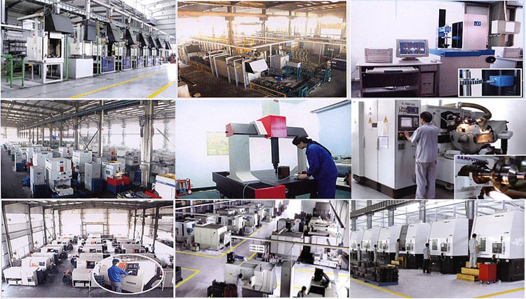
Founded in 1995, HangZhou Ever-Electrical power Power machinery Co.,Ltd has 22 several years of reducer manufacturing experience and reliability. The company has professional engineer crew, sophisticated technological innovation production and competent employees, with located in HangZhou of ZheJiang province which has reliable industrial base and created transportation.
FAQ
1.Q:Are you the manufacturing unit or investing business?
A:We are the skilled Factory with 22 many years of knowledge.
2.Q:Can you customise according to our demands?
A:Of course, we can design nonstandard goods in accordance to customer’s drawing and sample.
3.Q:How extended is the supply date?
A:10-20 operating times.
4.Q:Where is your manufacturing facility?
A:We are in HangZhou of ZheJiang Province, you can get here by substantial velocity train or fly to Jinan.
Welcome to go to us!