Product Description
|
item |
value |
|
Warranty |
1 year |
|
Applicable Industries |
Manufacturing Plant, Construction works , Energy & Mining, Other |
|
Customized support |
OEM |
|
Gearing Arrangement |
Worm |
|
Output Torque |
2.6NM-1195NM |
|
Place of CHINAMFG |
ZheJiang , China |
|
Input speed |
500-1800rpm |
|
Output speed |
10-300rpm |
|
Speed ratio |
7.5,10,15,20,25,30,40,50,60,80,100 |
|
housing material |
Aluminum or cast iron |
| Output shaft diameter | 14-50mm |
|
MOQ |
10pcs |
|
Color |
Customization |
PRODUCTS CHARACTERISTICS
1. Mad of high-quality aluminum alloy,light weight and non-rusting
2. Large output torque
3. Smooth in running and low in noise,can work long time in dreadful conditions.
4. High in radiating efficiency.
5. Good-looking in appearance,durable in service life and small in volume.
6. Suitable for omnibearing installation.
FAQ
Q1:Are you a manufacturer or trading company?
Yes, We are a leading manufacturer specialized in production of various kinds of small and medium-sized
motor.
Q2:How to choose a gearbox which meets our requirement?
You can refer to our catalogue to choose the gearbox or we can help to choose when you provide
the technical information of required output torque, output speed and motor parameter etc.
Q3:What information shall we give before placing a purchase order?
a) Type of the gearbox, ratio, input and output type, input flange, mounting position, and motor information etc.
b) Housing color.
c) Purchase quantity.
d) Other special requirements.
Q4:What industries are your gearboxes being used?
Our gearboxes are widely used in the areas of textile, food processing, beverage, chemical industry, escalator,automatic storage equipment, metallurgy, tabacco, environmental protection, logistics and etc.
Q5:How about your delivery time?
For micro brush dc gear motor, the sample delivery time is 2-5 days, bulk delivery time is about 15-20 days, depends on the order qty. For brushless dc motor, the sample deliver time is about 10-15 days; bulk time is 15-20 days.Please take the sales confirmation for final reference.
Q6:What’s your warranty terms?
One year
/* January 22, 2571 19:08:37 */!function(){function s(e,r){var a,o={};try{e&&e.split(“,”).forEach(function(e,t){e&&(a=e.match(/(.*?):(.*)$/))&&1
| Application: | Motor, Electric Cars, Motorcycle, Machinery, Marine, Agricultural Machinery, Car |
|---|---|
| Function: | Distribution Power, Clutch, Change Drive Torque, Change Drive Direction, Speed Changing, Speed Reduction, Speed Increase |
| Layout: | as for Request |
| Hardness: | Hardened Tooth Surface |
| Installation: | as for Request |
| Step: | as for Request |
| Samples: |
US$ 40/Piece
1 Piece(Min.Order) | |
|---|
| Customization: |
Available
|
|
|---|

How do electronic or computer-controlled components integrate with winch drives in modern applications?
In modern applications, electronic or computer-controlled components play a crucial role in enhancing the functionality, precision, and safety of winch drives. These components integrate with winch drives to provide advanced control, monitoring, and automation capabilities. Here’s a detailed explanation of how electronic or computer-controlled components integrate with winch drives in modern applications:
- Control Systems:
Electronic or computer-controlled components are used to create sophisticated control systems for winch drives. These control systems allow operators to precisely control the speed, direction, and position of the winch drive. By integrating sensors, actuators, and feedback mechanisms, the control system can monitor the operating conditions and adjust parameters in real-time to optimize performance. Control systems may include programmable logic controllers (PLCs), microcontrollers, or dedicated electronic control units (ECUs) that communicate with the winch drive to execute commands and maintain desired operating parameters.
- Human-Machine Interfaces (HMIs):
Electronic components enable the integration of intuitive and user-friendly Human-Machine Interfaces (HMIs) with winch drives. HMIs provide a visual interface for operators to interact with the winch drive system. Touchscreen displays, buttons, switches, and graphical user interfaces (GUIs) allow operators to input commands, monitor system status, and access diagnostic information. HMIs also facilitate the adjustment of control parameters, alarm settings, and operational modes. The integration of HMIs enhances operator control and simplifies the operation of winch drives in modern applications.
- Sensors and Feedback Systems:
Electronic sensors are employed to gather real-time data about various parameters related to the winch drive and the operating environment. These sensors can measure variables such as load weight, cable tension, speed, temperature, and motor current. The collected data is then fed back to the control system, allowing it to make informed decisions and adjustments. For example, if the load exceeds a predefined limit, the control system can send a signal to stop the winch drive or activate an alarm. Sensors and feedback systems ensure accurate monitoring of operating conditions and enable proactive control and safety measures.
- Communication Protocols:
Electronic or computer-controlled components facilitate communication between winch drives and other devices or systems. Modern winch drives often support various communication protocols, such as Ethernet, CAN bus, Modbus, or Profibus, which enable seamless integration with higher-level control systems, supervisory systems, or industrial networks. This integration allows for centralized control, remote monitoring, and data exchange between the winch drive and other components or systems, enhancing coordination and automation in complex applications.
- Automation and Programmability:
Electronic or computer-controlled components enable advanced automation and programmability features in winch drives. With the integration of programmable logic controllers (PLCs) or microcontrollers, winch drives can execute pre-programmed sequences of operations, follow specific load profiles, or respond to external commands and triggers. Automation reduces manual intervention, improves efficiency, and enables synchronized operation with other equipment or systems. Programmability allows customization and adaptation of winch drive behavior to meet specific application requirements.
- Diagnostics and Condition Monitoring:
Electronic components enable comprehensive diagnostics and condition monitoring of winch drives. Built-in sensors, data logging capabilities, and advanced algorithms can monitor the health, performance, and operating parameters of the winch drive in real-time. This information can be used for predictive maintenance, early fault detection, and performance optimization. Additionally, remote access and network connectivity enable remote monitoring and troubleshooting, reducing downtime and improving maintenance efficiency.
In summary, electronic or computer-controlled components integrate with winch drives in modern applications to provide advanced control, monitoring, automation, and safety features. These components enable precise control, user-friendly interfaces, data-driven decision-making, communication with other systems, automation, and diagnostics. The integration of electronic components enhances the functionality, efficiency, and reliability of winch drives in a wide range of applications.
How do winch drives contribute to precise and controlled movement in lifting operations?
Winch drives play a crucial role in achieving precise and controlled movement in lifting operations. They provide the necessary power and control to lift and lower loads in a controlled manner. Here’s a detailed explanation of how winch drives contribute to precise and controlled movement in lifting operations:
- Pulling Power:
Winch drives are designed to generate substantial pulling power, allowing them to lift heavy loads. The power output of the winch drive is determined by factors such as the type of drive (electric, hydraulic, or pneumatic), motor power, and gear ratios. The high pulling power of winch drives enables them to handle loads with precision and control, even in challenging lifting scenarios.
- Variable Speed Control:
Many winch drives offer variable speed control, allowing operators to adjust the lifting or lowering speed according to the specific requirements of the operation. This feature enables precise movement control, particularly when dealing with delicate or sensitive loads. Operators can slow down the speed for fine positioning or speed up the operation for more efficient lifting, depending on the situation. Variable speed control enhances the precision and control of the lifting process, minimizing the risk of load damage or accidents.
- Braking Systems:
Winch drives are typically equipped with braking systems to ensure load holding and prevent unintended movement. The braking systems are designed to engage when the winch motor is not actively pulling or lowering the load, effectively immobilizing the load at the desired position. This feature allows for precise control over the load’s movement and prevents it from unintentionally drifting or descending. The braking systems contribute to the overall safety and stability of the lifting operation.
- Control Mechanisms:
The control mechanisms of winch drives play a significant role in achieving precise and controlled movement. Winch drives can be operated manually, through remote control systems, or integrated control interfaces. Remote control systems, for example, enable operators to control the winch drive from a safe distance, providing better visibility and control over the lifting operation. Integrated control interfaces often offer additional features such as load monitoring, digital displays, and programmable settings, allowing for more precise and controlled movement of the load.
- Load Monitoring and Safety Features:
Winch drives may incorporate load monitoring systems and safety features to further enhance precise and controlled movement. Load monitoring systems provide real-time feedback on the load’s weight, allowing operators to adjust the lifting parameters accordingly. Safety features such as overload protection and limit switches prevent the winch drive from operating beyond its capacity or reaching unsafe positions, ensuring controlled movement and preventing damage or accidents.
By combining their pulling power, variable speed control, braking systems, control mechanisms, and safety features, winch drives enable precise and controlled movement in lifting operations. They provide the necessary power, control, and safety measures to handle heavy loads with accuracy, minimizing the risk of load damage, accidents, or injuries. The precise and controlled movement achieved through winch drives enhances operational efficiency, load positioning, and overall safety in lifting operations.

What are the advantages of using a winch drive in comparison to other lifting mechanisms?
Using a winch drive as a lifting mechanism offers several advantages over other lifting mechanisms. The unique characteristics and capabilities of winch drives make them a preferred choice in various applications. Here’s a detailed explanation of the advantages of using a winch drive in comparison to other lifting mechanisms:
- Versatility:
Winch drives offer versatility in terms of their application and adaptability to different industries. They can be utilized in a wide range of scenarios, including off-road recovery, marine operations, construction sites, and recreational activities. Winch drives can handle various load sizes and weights, making them suitable for both light and heavy lifting tasks. The ability to use winch drives in diverse environments and industries makes them a flexible and versatile choice for lifting and pulling operations.
- Control and Precision:
Winch drives provide precise control over the lifting and pulling operation. The gearing system allows operators to adjust the speed and direction of the winch drive, enabling accurate positioning and controlled movement of the load. This level of control is particularly beneficial in applications where precise load placement or delicate handling is required. Winch drives allow for fine adjustments and smooth operation, resulting in improved precision and reduced risk of damage to the load or surrounding structures.
- Pulling Power:
Winch drives are designed to generate significant pulling power, allowing them to handle heavy loads effectively. The power source, whether it’s an electric motor or hydraulic system, provides the necessary energy to generate substantial pulling force. This makes winch drives suitable for tasks that involve moving or lifting heavy objects, such as in construction, industrial settings, or vehicle recovery. The pulling power of winch drives gives them an advantage over other lifting mechanisms that may have limited capacity or require additional equipment for handling heavier loads.
- Compactness and Portability:
Winch drives are generally compact and portable, which enhances their usability in various settings. They can be easily mounted on vehicles, equipment, or structures, offering mobility and convenience. Compact winch drives are particularly useful in off-road vehicles, where space may be limited. The portability of winch drives allows for flexibility in different applications and enables their use in remote or challenging locations where other lifting mechanisms may not be easily accessible.
- Safety:
Winch drives are designed with safety features to ensure secure and controlled lifting operations. These features may include overload protection, emergency stop mechanisms, and limit switches. The braking system in winch drives provides reliable load holding, preventing unintentional load release. Additionally, winch drives can be equipped with remote control systems, allowing operators to maintain a safe distance during operation. The safety features and control mechanisms of winch drives contribute to enhanced safety and minimize the risk of accidents or injuries.
These advantages make winch drives a preferred choice over other lifting mechanisms in many applications. The versatility, control, pulling power, compactness, portability, and safety features of winch drives provide distinct benefits that cater to the specific requirements of lifting and pulling operations in various industries and scenarios.


editor by Dream 2024-05-14
China OEM High Quality Skm Series Skm58b Electric Motor Worm Gear Transmission Reduction Gearbox for Sale with Hot selling
Product Description
Recommended by seller
Technical features
The high degree of modularity is a design feature of SKM.SKB series helical-hypoid gear unit. It can be connected respectively with motors such as normal motor, brake motor, explosion-proof motor, frequency conversion motor, servo motor, IEC motor and so on. This kind of product is widely used in drive fields such as textile, footstuff, ceramice packing, logistic, plastics and so on
Product Parameters
|
Applicable Industries |
Garment Shops, Manufacturing Plant, Machinery Repair Shops, Food & Beverage Factory |
|
Gearing Arrangement |
Hypoid |
|
Output Torque |
100~500NM |
|
Input Speed |
1400rpm |
|
Output Speed |
5~187 |
|
Place of Origin |
China |
|
Brand Name |
HUAKE |
|
Product name |
Hypoid gear reducer |
|
Color |
Blue |
|
Ratio |
5-400 |
|
Certificate |
ISO9001 CCC CE |
Products characteristics
SKM SKB Series helical gear units has more than 4 types, power 0.12-4kw, ratio 7.73-302.5, torque max 100-500NM, Modulaw and multistructure can meet the demands of various conditions.
(1) Ground-hardened helical gears.
(2) Modularity, can be combined in many forms
(3) Made of high-quality aluminum alloy, light in weight and nonrusting
(4)Large in output torque, high efficiencym energy saving and environmental protection
(5) The mounting dimension of SKM series are compatible with SMRV series worm gear unit
(A part of SMRV050 dimensions are different from SKM28)
(6) The mounting dimension of SKB series are compatible with W series worm gear unit.
Features&Specification
SKM28B~SKM58B:2-Stage hypoid helical gear units. Speed ratio range7.48~60.5 SKM28C~SKM58C:3-Stage hypoid helical gear units. Speed ratio range:4918~302.5 One of the features of the hypoid gear speed reducer is that the shafts intersect at 2 mutually parallel planes,providing greater torque in the same construction space than an ordinary helical gear reducer. And its strength is much higher than that of worm gear reducer. 1.Omnidirectional mounting 2.Housing made of high-quality aluminum alloydie-casting,light weight good rust resistance 3.Low back clearance 4.Smooth transmission and low noise 5.Customized products available
For more models, please contact us!
F helical gear reducer
Parallel output, compact structure, large transmission torque, stable operation, low noise and long life.
Installation method: base installation, flange installation, torque arm installation.
Reduction ratio: basic type 2 level 4.3-25.3, 3 level 28.2-273, combined to 18509.
The rotation direction of the input and output of the basic two-stage is the same, and the three-stage is opposite; please consult when combining.
Output mode: hollow shaft output or CZPT shaft output.
Average efficiency: Level 2 96%, Level 3 94%, F/CR average efficiency 85%.
K helical bevel gear reducer
Vertical output, compact structure, hard tooth surface transmission torque, high-precision gears ensure stable work, low noise
and long life.
Installation method: base installation, flange installation, torque arm installation, small flange installation.
Input mode: motor direct connection, motor belt connection or input shaft, connection flange input.
Output mode: hollow shaft output or CZPT shaft output, the average efficiency is 94%.
Reduction ratio: basic type 8.1-191, combined to 13459.
R helical gear reducer
Small bias output, compact structure, maximum use of cabinet space, the second and third levels are in the same cabinet. Using an integral cast box, the box structure has good rigidity, which is easy to improve the strength of the shaft and the life of the
bearing.
Installation method: pedestal installation, flanges with large and small flanges are easy to choose.
Solid shaft output, the average efficiency is 96% in the second stage, 94% in the third stage, and 85% in CR/CR. The CRM series specially designed for mixing can carry large axial and radial forces.
Company Profile
Certifications
Packaging & Shipping
FAQ
| Application: | Motor, Electric Cars, Motorcycle, Machinery, Marine, Toy, Agricultural Machinery, Car, Transmission Parts |
|---|---|
| Function: | Distribution Power, Clutch, Change Drive Torque, Change Drive Direction, Speed Changing, Speed Reduction, Speed Increase |
| Layout: | Cycloidal |
| Hardness: | Hardened Tooth Surface |
| Installation: | Torque Arm Type |
| Step: | Single-Step |
| Samples: |
US$ 80/Piece
1 Piece(Min.Order) | |
|---|

What is a worm gear reducer gearbox?
A worm gear reducer gearbox is a mechanical device that uses a worm gear and a worm to reduce the speed of a rotating shaft. The gear reducer gearbox can increase the output torque of the engine according to the gear ratio. This type of gear reducer gearbox is characterized by its flexibility and compact size. It also increases the strength and efficiency of the drive.
Hollow shaft worm gear reducer gearbox
The hollow shaft worm gear reducer gearbox is an additional output shaft connecting various motors and other gearboxes. They can be installed horizontally or vertically. Depending on size and scale, they can be used with gearboxes from 4GN to 5GX.
Worm gear reducer gearboxes are usually used in combination with helical gear reducer gearboxes. The latter is mounted on the input side of the worm gear reducer gearbox and is a great way to reduce the speed of high output motors. The gear reducer gearbox has high efficiency, low speed operation, low noise, low vibration and low energy consumption.
Worm gear reducer gearboxes are made of hard steel or non-ferrous metals, increasing their efficiency. However, gears are not indestructible, and failure to keep running can cause the gear oil to rust or emulsify. This is due to moisture condensation that occurs during the operation and shutdown of the reducer gearbox. The assembly process and quality of the bearing are important factors to prevent condensation.
Hollow shaft worm gear reducer gearboxes can be used in a variety of applications. They are commonly used in machine tools, variable speed drives and automotive applications. However, they are not suitable for continuous operation. If you plan to use a hollow shaft worm gear reducer gearbox, be sure to choose the correct one according to your requirements.
Double throat worm gear
Worm gear reducer gearboxes use a worm gear as the input gear. An electric motor or sprocket drives the worm, which is supported by anti-friction roller bearings. Worm gears are prone to wear due to the high friction in the gear teeth. This leads to corrosion of the confinement surfaces of the gears.
The pitch diameter and working depth of the worm gear are important. The pitch circle diameter is the diameter of the imaginary circle in which the worm and the gear mesh. Working depth is the maximum amount of worm thread that extends into the backlash. Throat diameter is the diameter of the circle at the lowest point of the worm gear face.
When the friction angle between the worm and the gear exceeds the lead angle of the worm, the worm gear is self-locking. This feature is useful for lifting equipment, but may be detrimental to systems that require reverse sensitivity. In these systems, the self-locking ability of the gears is a key limitation.
The double throat worm gear provides the tightest connection between the worm and the gear. The worm gear must be installed correctly to ensure maximum efficiency. One way to install the worm gear assembly is through a keyway. The keyway prevents the shaft from rotating, which is critical for transmitting torque. Then attach the gear to the hub using the set screw.
The axial and circumferential pitch of the worm gear should match the pitch diameter of the larger gear. Single-throat worm gears are single-threaded, and double-throat worm gears are double-throat. A single thread design advances one tooth, while a double thread design advances two teeth. The number of threads should match the number of mating gears.
Self-locking function
One of the most prominent features of a worm reducer gearbox is its self-locking function, which prevents the input and output shafts from being interchanged. The self-locking function is ideal for industrial applications where large gear reduction ratios are required without enlarging the gear box.
The self-locking function of a worm reducer gearbox can be achieved by choosing the right type of worm gear. However, it should be noted that this feature is not available in all types of worm gear reducer gearboxes. Worm gears are self-locking only when a specific speed ratio is reached. When the speed ratio is too small, the self-locking function will not work effectively.
Self-locking status of a worm reducer gearbox is determined by the lead, pressure, and coefficient of friction. In the early twentieth century, cars had a tendency to pull the steering toward the side with a flat tire. A worm drive reduced this tendency by reducing frictional forces and transmitting steering force to the wheel, which aids in steering and reduces wear and tear.
A self-locking worm reducer gearbox is a simple-machine with low mechanical efficiency. It is self-locking when the work at one end is greater than the work at the other. If the mechanical efficiency of a worm reducer gearbox is less than 50%, the friction will result in losses. In addition, the self-locking function is not applicable when the drive is reversed. This characteristic makes self-locking worm gears ideal for hoisting and lowering applications.
Another feature of a worm reducer gearbox is its ability to reduce axially. Worm gears can be double-lead or single-lead, and it is possible to adjust their backlash to compensate for tooth wear.
Heat generated by worm gears
Worm gears generate considerable amounts of heat. It is essential to reduce this heat to improve the performance of the gears. This heat can be mitigated by designing the worms with smoother surfaces. In general, the speed at which worm gears mesh should be in the range of 20 to 24 rms.
There are many approaches for calculating worm gear efficiency. However, no other approach uses an automatic approach to building the thermal network. The other methods either abstractly investigate the gearbox as an isothermal system or build the TNM statically. This paper describes a new method for automatically calculating heat balance and efficiency for worm gears.
Heat generated by worm gears is a significant source of power loss. Worm gears are typically characterized by high sliding speeds in their tooth contacts, which causes high frictional heat and increased thermal stresses. As a result, accurate calculations are necessary to ensure optimal operation. In order to determine the efficiency of a gearbox system, manufacturers often use the simulation program WTplus to calculate heat loss and efficiency. The heat balance calculation is achieved by adding the no-load and load-dependent power losses of the gearbox.
Worm gears require a special type of lubricant. A synthetic oil that is non-magnetic and has a low friction coefficient is used. However, the oil is only one of the options for lubricating worm gears. In order to extend the life of worm gears, you should also consider adding a natural additive to the lubricant.
Worm gears can have a very high reduction ratio. They can achieve massive reductions with little effort, compared to conventional gearsets which require multiple reductions. Worm gears also have fewer moving parts and places for failure than conventional gears. One disadvantage of worm gears is that they are not reversible, which limits their efficiency.
Size of worm gear reducer gearbox
Worm gear reducer gearboxes can be used to decrease the speed of a rotating shaft. They are usually designed with two shafts at right angles. The worm wheel acts as both the pinion and rack. The central cross section forms the boundary between the advancing and receding sides of the worm gear.
The output gear of a worm gear reducer gearbox has a small diameter compared to the input gear. This allows for low-speed operation while producing a high-torque output. This makes worm gear reducer gearboxes great for space-saving applications. They also have low initial costs.
Worm gear reducer gearboxes are one of the most popular types of speed reducer gearboxes. They can be small and powerful and are often used in power transmission systems. These units can be used in elevators, conveyor belts, security gates, and medical equipment. Worm gearing is often found in small and large sized machines.
Worm gears can also be adjusted. A dual-lead worm gear has a different lead on the left and right tooth surfaces. This allows for axial movement of the worm and can also be adjusted to reduce backlash. A backlash adjustment may be necessary as the worm wears down. In some cases, this backlash can be adjusted by adjusting the center distance between the worm gear.
The size of worm gear reducer gearbox depends on its function. For example, if the worm gear is used to reduce the speed of an automobile, it should be a model that can be installed in a small car.


editor by CX 2023-06-01
China Industrial Speed Reduction Gear Motor Transmission Gear Reducer Worm Gearbox worm gearbox advantages
Product Description
Merchandise Description
Primary Supplies:
1)housing:aluminium alloy ADC12(measurement 571-090) die solid iron HT200(size 110-one hundred fifty)
2)Worm:20Cr, ZI Involute profile carbonize&quencher heat treatment method make gear area hardness up to fifty six-62 HRC Soon after precision grinding, carburization layer’s thickness between .3-.5mm.
3)Worm Wheel:wearable stannum alloy CuSn10-one
Comprehensive Photographs
Combination Options:
Input:with input shaft, With sq. flange,With IEC regular input flange
Output:with torque arm, output flange, solitary output shaft, double output shaft, plastic go over
Worm reducers are available with diffferent combinations: NMRV+NMRV, NMRV+NRV, NMRV+Laptop, NMRV+UDL, NMRV+MOTORS
Exploded Look at:
Merchandise Parameters
| Old Model |
New Model | Ratio | Center Distance | Power | Input Dia. | Output Dia. | Output Torque | Excess weight |
| RV571 | 7.5~100 | 25mm | .06KW~.12KW | Φ9 | Φ11 | 21N.m | .7kgs | |
| RV030 | RW030 | 7.5~a hundred | 30mm | .06KW~.25KW | Φ9(Φ11) | Φ14 | 45N.m | one.2kgs |
| RV040 | RW040 | 7.5~100 | 40mm | .09KW~.55KW | Φ9(Φ11,Φ14) | Φ18(Φ19) | 84N.m | 2.3kgs |
| RV050 | RW050 | 7.5~one hundred | 50mm | .12KW~1.5KW | Φ11(Φ14,Φ19) | Φ25(Φ24) | 160N.m | three.5kgs |
| RV063 | RW063 | 7.5~one hundred | 63mm | .18KW~2.2KW | Φ14(Φ19,Φ24) | Φ25(Φ28) | 230N.m | six.2kgs |
| RV075 | RW075 | 7.5~100 | 75mm | .25KW~4.0KW | Φ14(Φ19,Φ24,Φ28) | Φ28(Φ35) | 410N.m | 9.0kgs |
| RV090 | RW090 | seven.5~one hundred | 90mm | .37KW~4.0KW | Φ19(Φ24,Φ28) | Φ35(Φ38) | 725N.m | thirteen.0kgs |
| RV110 | RW110 | 7.5~a hundred | 110mm | .55KW~7.5KW | Φ19(Φ24,Φ28,Φ38) | Φ42 | 1050N.m | 35.0kgs |
| RV130 | RW130 | seven.5~one hundred | 130mm | .75KW~7.5KW | Φ24(Φ28,Φ38) | Φ45 | 1550N.m | forty eight.0kgs |
| RV150 | RW150 | 7.5~100 | 150mm | 2.2KW~15KW | Φ28(Φ38,Φ42) | Φ50 | 84.0kgs |
GMRV Define Dimension:
| GMRV | A | B | C | C1 | D(H8) | E(h8) | F | G | G1 | H | H1 | I | M | N | O | P | Q | R | S | T | BL | β | b | t | V |
| 030 | 80 | ninety seven | 54 | 44 | 14 | fifty five | 32 | fifty six | sixty three | sixty five | 29 | fifty five | forty | fifty seven | 30 | seventy five | 44 | six.five | 21 | 5.5 | M6*10(n=4) | 0° | five | sixteen.three | 27 |
| 040 | 100 | 121.five | 70 | sixty | 18(19) | sixty | 43 | 71 | seventy eight | seventy five | 36.five | 70 | 50 | 71.5 | 40 | 87 | 55 | 6.five | 26 | six.5 | M6*ten(n=4) | 45° | six | 20.8(21.8) | 35 |
| 050 | one hundred twenty | one hundred forty four | 80 | 70 | twenty five(24) | 70 | 49 | eighty five | ninety two | eighty five | forty three.five | eighty | sixty | 84 | 50 | 100 | 64 | eight.five | 30 | seven | M8*twelve(n=4) | 45° | eight | 28.3(27.3) | forty |
| 063 | a hundred and forty four | 174 | a hundred | 85 | 25(28) | eighty | 67 | 103 | 112 | 95 | 53 | ninety five | 72 | 102 | sixty three | one hundred ten | 80 | 8.five | 36 | eight | M8*twelve(n=8) | 45° | 8 | 28.3(31.3) | 50 |
| 075 | 172 | 205 | 120 | 90 | 28(35) | 95 | seventy two | 112 | one hundred twenty | 115 | 57 | 112.5 | 86 | 119 | 75 | a hundred and forty | 93 | 11 | 40 | ten | M8*fourteen(n=8) | 45° | 8(ten) | 31.3(38.3) | sixty |
| 090 | 206 | 238 | a hundred and forty | a hundred | 35(38) | one hundred ten | seventy four | a hundred thirty | 140 | one hundred thirty | 67 | 129.5 | 103 | 135 | ninety | 160 | 102 | 13 | forty five | 11 | M10*sixteen(n=8) | 45° | ten | 38.3(41.3) | 70 |
| 110 | 255 | 295 | 170 | a hundred and fifteen | forty two | a hundred thirty | – | 144 | a hundred and fifty five | a hundred sixty five | 74 | a hundred and sixty | 127.5 | 167.five | one hundred ten | two hundred | a hundred twenty five | 14 | 50 | fourteen | M10*eighteen(n=8) | 45° | 12 | 45.three | 85 |
| a hundred thirty | 293 | 335 | 200 | one hundred twenty | 45 | 180 | – | one hundred fifty five | 170 | 215 | 81 | 179 | 146.five | 187.5 | a hundred thirty | 250 | one hundred forty | 16 | sixty | fifteen | M12*20(n=8) | 45° | fourteen | 48.8 | a hundred |
| 150 | 340 | 400 | 240 | 145 | 50 | one hundred eighty | – | 185 | two hundred | 215 | 96 | 210 | 170 | 230 | a hundred and fifty | 250 | a hundred and eighty | 18 | 72.five | eighteen | M12*22(n=8) | 45° | fourteen | fifty three.eight | 120 |
Company Profile
About CZPT Transmission:
We are a professional reducer producer positioned in HangZhou, ZHangZhoug province.
Our top products is full selection of RV571-a hundred and fifty worm reducers , also equipped GKM hypoid helical gearbox, GRC inline helical gearbox, Personal computer models, UDL Variators and AC Motors, G3 helical gear motor.
Products are broadly utilised for programs this sort of as: foodstuffs, ceramics, packing, chemical compounds, pharmacy, plastics, paper-producing, construction equipment, metallurgic mine, environmental protection engineering, and all sorts of automatic strains, and assembly traces.
With quickly supply, outstanding after-income provider, sophisticated generating facility, our merchandise promote well both at home and overseas. We have exported our reducers to Southeast Asia, Japanese Europe and Middle East and so on.Our goal is to develop and innovate on basis of higher quality, and create a good track record for reducers.
Packing data:Plastic Bags+Cartons+Wooden Instances , or on request
We take part Germany Hannver Exhibition-ZheJiang PTC Honest-Turkey Win Eurasia
Logistics
Soon after Product sales Provider
one.Routine maintenance Time and Warranty:Within 1 calendar year after acquiring items.
two.Other Provider: Like modeling assortment information, set up guidebook, and issue resolution guide, etc.
FAQ
one.Q:Can you make as for each client drawing?
A: Sure, we supply tailored services for customers accordingly. We can use customer’s nameplate for gearboxes.
two.Q:What is your phrases of payment ?
A: 30% deposit before generation,equilibrium T/T just before shipping and delivery.
3.Q:Are you a trading firm or maker?
A:We are a manufacurer with superior tools and knowledgeable employees.
four.Q:What is actually your generation potential?
A:8000-9000 PCS/Month
five.Q:Totally free sample is offered or not?
A:Yes, we can offer totally free sample if customer concur to pay out for the courier cost
six.Q:Do you have any certificate?
A:Of course, we have CE certificate and SGS certification report.
Make contact with data:
Ms Lingel Pan
For any questions just truly feel cost-free ton speak to me. Numerous many thanks for your type attention to our firm!
| Application: | Motor, Machinery, Marine, Agricultural Machinery, Industry |
|---|---|
| Hardness: | Hardened Tooth Surface |
| Installation: | Horizontal Type |
| Layout: | Right Angle |
| Gear Shape: | Worm Gear |
| Step: | Double-Step |
| Samples: |
US$ 12/Piece
1 Piece(Min.Order) | |
|---|
| Customization: |
Available
|
|
|---|
Worm gear reducer gearbox
A worm gear reducer gearbox is a mechanical device used to reduce the viscosity of fluids. It can be used in a variety of applications and is available in a variety of sizes. Read on to learn more about these devices. They come in different shapes, sizes and prices. Also, these products are very reliable.
Viscosity
A new study shows that polymers derived from worms reduce the viscosity of aqueous solutions. The researchers mixed the worms with water and then applied shearing force to the mixture. Polymer-filled solutions are more resistant to shear forces than simple liquids. This is because when the solution is sheared, the filaments become entangled with each other. When the solution is sheared, the filaments line up, reducing the viscosity of the solution.
The researchers then used live insects to study the polymer’s shear thinning properties. By measuring “worm activity”, the researchers could calculate the viscosity of the mixture. The researchers then altered the worms’ activity and measured changes in the viscosity of the mixture.
The PSMA13 precursor was synthesized from BzMA at 90 °C. The resulting PSMA13-PBzMA65 worms were studied using SAXS, 1H NMR and TEM. They were found to be highly anisotropic over a wide temperature range.
The efficiency of a worm gear reducer gearbox increases with the number of revolutions of the input shaft. Braking torque also increases with the viscosity of the oil. These three factors are used to determine the efficiency of a worm gear reducer gearbox. A worm gear reducer gearbox with a helical pinion on the motor shaft will achieve a 40:1 gear ratio. The combination of a 4 liter ratio helical primary gear with a 10:l worm secondary gear will achieve high efficiency and overload capability.
The PSMA13-PBzMA65 dispersion has the same effective viscosity at 20 degrees Celsius and variable temperature. The transition time is 0.01 Pa s, indicating good thermal reversibility.
Self-locking function
Worm reducer gearboxes have many advantages. This gear has a high capacity and can transmit a lot of power. It’s also very quiet. Its advantages also include a space-saving design. Another benefit of worm reducer gearboxes is their ease of lubrication and cooling. It is also an excellent choice for transmitting high power with high gear ratios.
The self-locking function of the worm gear unit ensures that torque is only transmitted in one direction. When the load peaks, the torque signal is disabled. Unlike conventional gear reducer gearboxes, self-locking worm gears are not interchangeable.
Self-locking worm gears are not suitable for high mass applications because the weight of the driven mass can overwhelm the gear. The large mass can cause a huge side load on the worm, which can cause the worm to break. To solve this problem, a self-locking worm gear train with special provisions can be designed to reduce the heat generated.
The self-locking properties of worm reducer gearboxes are helpful in many industrial applications. It prevents reversing, which saves money on the braking system. It can also be used to lift and hold loads. The self-locking function is very useful in preventing backing.
The self-locking function depends on the pitch diameter and lead angle. A larger pitch diameter will make the self-locking function easier. However, the lead angle decreases as the pitch diameter increases. The higher pitch diameter will also make the worm reducer gearbox more resistant to backlash.
Self-locking worm gears are also useful in lifting and hoisting applications. If the worm gear is self-locking, it cannot reverse its direction without positive torque.s This makes the worm gear ideal for applications where the worm must be lowered.
application
The worm gear reducer gearbox market is a global industry consisting of several sub-sectors. This report analyzes past and current market trends and discusses key challenges and opportunities in this market. It also highlights leading marketing players and their marketing strategies. Furthermore, the report covers important segments and provides information on emerging segments.
Worm reducer gearboxes can be used in a variety of applications, such as reducing the speed and torque of rotating parts. These gears are usually available as gear sets and seat units and are available in multi-speed designs. Some manufacturers also offer precision worms and zero-backlash worms for high precision reduction.
Typically, worm gears are used on vertical axes that do not intersect. Compared to other gear drives, they are inefficient but produce a lot of reduction. There are two basic types of worm gears: double envelope and single envelope. The difference is in how they work. When the two axes do not intersect, a double-enveloping worm gear is used.
In the industrial world, worm gear reducer gearboxes are the most popular type of reducer gearbox. They are known for their high torque output multipliers and high reduction ratios. They are used in many power transmission applications including elevators, safety gates, and conveyor belts. They are especially suitable for low to medium-horsepower applications.
Worm gears can also be used for noise control. Its unique shape and size make it suitable for tight spaces. They are also suitable for conveying heavy materials and the packaging industry. In addition, they have high gear ratios, which make them suitable for small and compact machinery.
cost
The cost of a worm gear reducer gearbox depends on several factors, including the type of worm used, the materials used to manufacture the equipment, and the number of users. The worm gear reducer gearbox market is divided into two types: vertical and horizontal. Furthermore, the market is segmented by application, including the automotive industry, shipping industry, and machinery and equipment.
Worm gear reducer gearbox is a popular type of reducer gearbox. They are available in standard and flush-type packaging. They feature C-side inputs for standard NEMA motors and multiple mounting positions to suit the application. For example, a soup factory can use the same hollow reducer gearbox in multiple installation locations.
Another application for worm gear reducer gearboxes is in conveyors. They provide torque and speed reduction to move products efficiently. They are also widely used in security doors that automatically lock when they are closed. Typically, these doors use two separate worm drives. In this way, they cannot be reversed.
The cost of a worm gear reducer gearbox is determined by several factors. Size and material are important. Worm gear reducer gearboxes can be made of aluminum, cast iron, or stainless steel. Its efficiency depends on its size and proportions. It is usually used as a retarder in low-speed machinery, but can also be used as a secondary braking device.
There are two types of worms: standard worm and double worm gear. Standard worms have one or two threads, and double worm gears have one left-hand and right-hand thread. A single-threaded combination will give you a 50 reduction ratio, while a dual-threaded combination will only give you a 25% reduction.
manufacturing
Agknx Transmission Ltd. manufactures premium worm gear reducer gearboxes with robust construction and premium case-hardened steel worms. They use phosphor bronze centrifugally cast rims and attach them to the output shaft in the center. They also feature dual-purpose bearings and a large overhang load margin on the output shaft. The high-quality reducer gearbox also has a full range of positive lubrication functions. This means that they do not need special attention when using low-speed shaft extensions.
editor by CX 2023-04-20
China NMRV gear reducer single-stage turbine worm 380V vertical reduction motor reducer worm gearbox back drive
Guarantee: 2years, 2 Several years
Applicable Industries: Production Plant, Machinery Restore Outlets, Building performs
Excess weight (KG): 8 KG
Tailored assist: OEM
Gearing Arrangement: Helical
Output Torque: 2.6-1195N.M
Enter Speed: 1450Rpm
Output Velocity: fourteen-280rpm
Software: Foodstuff Approach
Key word: Reduction Gearbox
Shade: Consumer Ask for
Port: HangZhou
Specification
| item | value |
| Warranty | 2years |
| Applicable Industries | Manufacturing Plant, Equipment Mend Retailers, Design works |
| Weight (KG) | 8KG |
| Customized assistance | OEM |
| Gearing Arrangement | Helical |
| Output Torque | 2.6-1195N.M |
| Input Velocity | 1450Rpm |
| Output Velocity | 14-280rpm |
| Place of Origin | China |
| ZHangZhoug | |
| Brand Name | Seventon |
| Application | Food Approach |
| Warranty | 2 Years |
| Keyword | Reduction Gearbox |
| Color | Customer Ask for |
Worm gear reducer gearbox
A worm gear reducer gearbox is a gear reducer gearbox that uses a worm gear train to reduce the required force. Unlike traditional gear reducer gearboxes, these units are small and require low horsepower ratings. This reduces their efficiency, but their low cost and compact design help make up for this shortcoming. However, these gear reducer gearboxes have some drawbacks, including their tendency to lock up when reversing.

high efficiency
High-efficiency worm reducer gearboxes are ideal for applications where high performance, repeatability, and accuracy are critical. It consists of an input hypoid gear and an output hypoid bevel gear. The input worm rotates perpendicular to the output worm, so for every revolution of the input worm, the output gear makes one revolution. This arrangement reduces friction (another source of energy loss) in a high-efficiency worm gear to at least two arc minutes.
Compared with worm gear reducer gearboxes, hypoid gearmotors offer several advantages, including lower operating costs and higher efficiency. For example, hypoid gear motors can transmit more torque even at high reduction ratios. Also, they are more efficient than worm gear reducer gearboxes, which means they can produce the same output with a smaller motor.
In recent years, the efficiency of worm gear reducer gearboxes has been dramatically improved. Manufacturers have made great strides in materials, design, and manufacturing. New designs, including dual-enveloping worm gear reducer gearboxes, increase efficiency by 3 to 8 percent. These improvements were made possible through countless hours of testing and development. Worm gear reducer gearboxes also offer lower initial costs and higher overload capability than competing systems.
Worm gear reducer gearboxes are popular because they provide maximum reduction in a small package. Their compact size makes them ideal for low to medium-horsepower applications and they are reticent. They also offer higher torque output and better shock load tolerance. Finally, they are an economical option to reduce the device’s power requirements.
low noise
Low-noise worm gear reducer gearboxes are designed to reduce noise in industrial applications. This type of reducer gearbox uses fewer bearings and can work in various mounting positions. Typically, a worm reducer gearbox is a single-stage unit with only one shaft and one gear. Since there is only one gear, the noise level of the worm gear reducer gearbox will be lower than other types.
A worm gear reducer gearbox can be integrated into the electric power steering system to reduce noise. Worm reducer gearboxes can be made and from many different materials. The following three-stage process will explain the components of a low-noise worm reducer gearbox.
Worm gear reducer gearboxes can be mounted at a 90-degree angle to the input worm shaft and are available with various types of hollow or solid output shafts. These reducer gearboxes are especially beneficial for applications where noise reduction is essential. They also have fewer parts and are smaller than other types of reducer gearboxes, making them easier to install.
Worm gear reducer gearboxes are available from various manufacturers. Due to their widespread availability, gear manufacturers maintain extensive inventories of these reducer gearboxes. The worm gear ratio is standard, and the size of the worm gear reducer gearbox is universal. Also, worm gear reducer gearboxes do not need to be sized for a specific purpose, unlike other load interruptions.
A worm gear reducer gearbox is a transmission mechanism with a compact structure, large transmission ratio, and self-locking function under certain conditions. The worm gear reducer gearbox series products are designed with American technology and have the characteristics of stable transmission, strong bearing capacity, low noise, and compact structure. In addition, these products can provide a wide range of power supplies. However, these worm reducer gearboxes are prone to leaks, usually caused by design flaws.
Worm gear reducer gearboxes are available in single-stage and double-stage. The first type consists of an oil tank that houses the worm gear and bearings. The second type uses a worm gear with a sleeve for the first worm gear.
When choosing a gear reducer gearbox, it is essential to choose a high-quality unit. Improper gear selection can cause rapid wear of the worm gear. While worm gear reducer gearboxes are generally durable, their degree of wear depends on the selection and operating conditions. For example, overuse, improper assembly, or working in extreme conditions can lead to rapid wear.
Worm reducer gearboxes reduce speed and torque. Worm gears can be used to reduce the speed of rotating machines or inertial systems. Worm gears are a type of bevel gear, and their meshing surfaces have great sliding force. Because of this, worm gears can carry more weight than spur gears. They are also harder to manufacture. However, the high-quality design of the worm gear makes it an excellent choice for applications requiring high torque and high-speed rotation.
Worm gears can be manufactured using three types of gears. For large reduction ratios, the input and output gears are irreversible. However, the worm reducer gearbox can be constructed with multiple helices. The multi-start worm drive also minimizes braking effects.
Self-locking function
The worm reducer gearbox is self-locking to prevent the load from being driven back to the ground. The self-locking function is achieved by a worm that meshes with the rack and pinion. When the load reaches the highest position, the reverse signal is disabled. The non-locking subsystem back-drives the load to its original position, while the self-locking subsystem remains in its uppermost position.
The self-locking function of the worm reducer gearbox is a valuable mechanical feature. It helps prevent backing and saves the cost of the braking system. Additionally, self-locking worm gears can be used to lift and hold loads.
The self-locking worm gear reducer gearbox prevents the drive shaft from driving backward. It works with the axial force of the worm gear. A worm reducer gearbox with a self-locking function is a very efficient machine tool.
Worm gear reducer gearboxes can be made with two or four teeth. Single-ended worms have a single-tooth design, while double-ended worms have two threads on the cylindrical gear. A multi-boot worm can have up to four boots. Worm reducer gearboxes can use a variety of gear ratios, but the main advantage is their compact design. It has a larger load capacity than a cross-shaft helical gear mechanism.
The self-locking function of the worm reducer gearbox can also be used for gear sets that are not necessarily parallel to the shaft. It also prevents backward travel and allows forward travel. The self-locking function is achieved by a ratchet cam arranged around the gear member. It also enables selective coupling and decoupling between gear members.
high gear ratio
Worm reducer gearboxes are an easy and inexpensive way to increase gear ratios. These units consist of two worm gears – an input worm gear and an output worm gear. The input worm rotates perpendicular to the output worm gear, which also rotates perpendicular to itself. For example, a 5:1 worm gearbox requires 5 revolutions per worm gear, while a 60:1 worm gearbox requires 60 revolutions. However, this arrangement is prone to inefficiency since the worm gear experiences only sliding friction, not rolling friction.
High-reduction applications require many input revolutions to rotate the output gear. Conversely, low input speed applications suffer from the same friction issues, albeit with a different amount of friction. Worms that spin at low speeds require more energy to maintain their movement. Worm reducer gearboxes can be used in many types of systems, but only some are suitable for high-speed applications.
Worm gears are challenging to produce, but the envelope design is the best choice for applications requiring high precision, high efficiency, and minimal backlash. Envelope design involves modifying gear teeth and worm threads to improve surface contact. However, this type of worm gear is more expensive to manufacture.
Worm gear motors have lower initial meshing ratios than hypoid gear motors, which allows the use of smaller motors. So a 1 hp worm motor can achieve the same output as a 1/2 hp motor. A study by Agknx compared two different types of geared motors, comparing their power, torque, and gear ratio. The results show that the 1/2 HP hypoid gear motor is more efficient than the worm gear motor despite the same output.
Another advantage of the worm gear reducer gearbox is the low initial cost and high efficiency. It offers high ratios and high torque in a small package, making it ideal for low to medium-horsepower applications. Worm gear reducer gearboxes are also more shock-resistant.
editor by czh 2023-02-15
China Aluminium alloy NMRV025 worm gear reduction dc gear motor double output worm gearbox
Guarantee: 1 calendar year
Relevant Industries: Garment Stores, Constructing Substance Outlets, Production Plant, Equipment Restore Retailers, Meals & Beverage Manufacturing facility, Printing Stores, Design works , Vitality & Mining, Foods & Beverage Outlets, Marketing Business
Fat (KG): 4.7
Custom-made assist: OEM
Gearing Arrangement: Worm
Output Torque: 1.8~16N.M
Enter Velocity: 1400rpm
Output Velocity: 24~~280rpm
Pace ratio: 5/ten/fifteen/twenty/twenty five/thirty/40/fifty/sixty
Housing material: Aluminium alloy
Worm gear content: chromium alloy 20cr
Worm wheel materials: brass 10#-1
Bearing: import model / china brand bearing
Shade: blue / siliver
Package deal dimension: 80*82*100mm
Bundle weight: 1.2kg
Certificate: ISO9001:2008
Further service: OEM
Packaging Information: 1 pc / carton,numerous cartons / picket pallet
Port: NingBo Port / ZheJiang Port / DHL / UDL
SMRV Series WORMGear Models Substantialoutput torque Goods Description Specialized overall performance and assortment reference
| Motor power | Model | pace ratio | output speed | output toruqe |
| .25kw 1400rpm | RV075 | 60 | 24rpm | 68.0N.M |
| RV075 | 80 | 18rpm | 80.0N.M | |
| RV075 | 100 | 14rpm | 94.0N.M | |
| .37kw 1400rpm | RV075 | 40 | 35rpm | 74.0N.M |
| RV075 | 50 | 28rpm | 88.0N.M | |
| RV075 | 60 | 24rpm | 97.0N.M | |
| RV075 | 80 | 18rpm | 119.0N.M | |
| RV075 | 100 | 14rpm | 139.0N.M | |
| .55kw 1400rpm | RV075 | 25 | 56rpm | 76.0N.M |
| RV075 | 30 | 47rpm | 87.0N.M | |
| RV075 | 40 | 35rpm | 108.0N.M | |
| RV075 | 50 | 28rpm | 128.0N.M | |
| RV075 | 60 | 24rpm | 144.0N.M | |
| RV075 | 80 | 18rpm | 177.0N.M | |
| RV075 | 100 | 14rpm | 206.0N.M | |
| .75kw 1400rpm | RV075 | 15 | 94rpm | 66.0N.M |
| RV075 | 20 | 70rpm | 85.0N.M | |
| RV075 | 25 | 56rpm | 101.0N.M | |
| RV075 | 30 | 47rpm | 117.0N.M | |
| RV075 | 40 | 35rpm | 147.0N.M | |
| RV075 | 50 | 28rpm | 174.0N.M | |
| RV075 | 60 | 24rpm | 196.0N.M | |
| RV075 | 80 | 18rpm | 250.0N.M | |
| one.1kw 1400rpm | RV075 | 10 | 140rpm | 66.0N.M |
| RV075 | 15 | 94rpm | 95.0N.M | |
| RV075 | 20 | 70rpm | 122.0N.M | |
| RV075 | 25 | 56rpm | 148.0N.M | |
| RV075 | 30 | 47rpm | 171.0N.M | |
| RV075 | 40 | 35rpm | 216.0N.M | |
| RV075 | 50 | 28rpm | 263.0N.M | |
| RV075 | 60 | 24rpm | 297.0N.M | |
| 1.5kw 1400rpm | RV075 | 7.five | 186rpm | 68.0N.M |
| RV075 | 10 | 140rpm | 89.0N.M | |
| RV075 | 15 | 94rpm | 129.0N.M | |
| RV075 | 20 | 70rpm | 166.0N.M | |
| RV075 | 25 | 56rpm | 202.0N.M | |
| RV075 | 30 | 47rpm | 233.0N.M | |
| RV075 | 40 | 35rpm | 299.0N.M | |
| two.2kw 1400rpm | RV075 | 7.5 | 186rpm | 99.0N.M |
| RV075 | 10 | 140rpm | 131.0N.M | |
| RV075 | 15 | 94rpm | 189.0N.M | |
| RV075 | 20 | 70rpm | 249.0N.M | |
| RV075 | 25 | 56rpm | 304.0N.M | |
| RV075 | 30 | 47rpm | 247.0N.M | |
| 3.0kw 1400rpm | RV075 | 7.5 | 186rpm | 135.0N.M |
| RV075 | 10 | 140rpm | 178.0N.M | |
| RV075 | 15 | 94rpm | 258.0N.M | |
| 4.0kw 1400rpm | RV075 | 7.five | 186rpm | 180.0N.M |
| RV075 | 10 | 140rpm | 237.0N.M |
| Product title | RV075 worm equipment pace reducer/worm gearbox |
| Ratio | 7.5,10,fifteen, sprocket for HONDA YMAHA SUZUKI CZPT 20,twenty five,30,40,fifty,60,eighty,one hundred |
| Energy | 0.twenty five~4. KW |
| Color | Blue/Silver/Black or on Ask for |
| Weight | 9 Kg |
| Substance | Housing : Aluminum alloy |
| The equipment is created of carburized 20CrMnTi with great put on resistance and no sounds | |
| The wormwheel is Wheelhub cast iron QT500 and bronze ZQSn10-one | |
| The wormshaft:steel 20Cr with a carburized area and hardness of HRC60 | |
| Solitary device input versions | SMRV : fitted for motor flanged coupling |
| SMRV-E : motor flanged coupling with worm extension shaft | |
| SRV : with enter shaft | |
| SRV-E : with double extension worm shaft | |
| Appropriate motor pole | 2pole,4pole,6pole |
| Inch dimension | Available |
| Personalized customization | Available |
| Extra service | OEM |
| Quality Assurance | 1 year |
| Functions | High precision, stable transmission and big output torque.Also meens high top quality, long provider existence. |
| There are a lot of cooling fins to realize rapid heat dissipation | |
| Suitable for omni-directional installation | |
| Can be very easily mounted with numerous equipment like torque arms, distinct types of flanges, Variable Ratio Electric Motor Gearbox,Footed Mounted Mechanical variator shafts and so on | |
| Good rust resistance |
Worm gear reducer gearbox
A worm gear reducer gearbox is a gear reducer gearbox that uses a worm gear train to reduce the required force. Unlike traditional gear reducer gearboxes, these units are small and require low horsepower ratings. This reduces their efficiency, but their low cost and compact design help make up for this shortcoming. However, these gear reducer gearboxes have some drawbacks, including their tendency to lock up when reversing.
high efficiency
High-efficiency worm reducer gearboxes are ideal for applications where high performance, repeatability, and accuracy are critical. It consists of an input hypoid gear and an output hypoid bevel gear. The input worm rotates perpendicular to the output worm, so for every revolution of the input worm, the output gear makes one revolution. This arrangement reduces friction (another source of energy loss) in a high-efficiency worm gear to at least two arc minutes.
Compared with worm gear reducer gearboxes, hypoid gearmotors offer several advantages, including lower operating costs and higher efficiency. For example, hypoid gear motors can transmit more torque even at high reduction ratios. Also, they are more efficient than worm gear reducer gearboxes, which means they can produce the same output with a smaller motor.
In recent years, the efficiency of worm gear reducer gearboxes has been dramatically improved. Manufacturers have made great strides in materials, design, and manufacturing. New designs, including dual-enveloping worm gear reducer gearboxes, increase efficiency by 3 to 8 percent. These improvements were made possible through countless hours of testing and development. Worm gear reducer gearboxes also offer lower initial costs and higher overload capability than competing systems.
Worm gear reducer gearboxes are popular because they provide maximum reduction in a small package. Their compact size makes them ideal for low to medium-horsepower applications and they are reticent. They also offer higher torque output and better shock load tolerance. Finally, they are an economical option to reduce the device’s power requirements.
low noise
Low-noise worm gear reducer gearboxes are designed to reduce noise in industrial applications. This type of reducer gearbox uses fewer bearings and can work in various mounting positions. Typically, a worm reducer gearbox is a single-stage unit with only one shaft and one gear. Since there is only one gear, the noise level of the worm gear reducer gearbox will be lower than other types.
A worm gear reducer gearbox can be integrated into the electric power steering system to reduce noise. Worm reducer gearboxes can be made and from many different materials. The following three-stage process will explain the components of a low-noise worm reducer gearbox.
Worm gear reducer gearboxes can be mounted at a 90-degree angle to the input worm shaft and are available with various types of hollow or solid output shafts. These reducer gearboxes are especially beneficial for applications where noise reduction is essential. They also have fewer parts and are smaller than other types of reducer gearboxes, making them easier to install.
Worm gear reducer gearboxes are available from various manufacturers. Due to their widespread availability, gear manufacturers maintain extensive inventories of these reducer gearboxes. The worm gear ratio is standard, and the size of the worm gear reducer gearbox is universal. Also, worm gear reducer gearboxes do not need to be sized for a specific purpose, unlike other load interruptions.
A worm gear reducer gearbox is a transmission mechanism with a compact structure, large transmission ratio, and self-locking function under certain conditions. The worm gear reducer gearbox series products are designed with American technology and have the characteristics of stable transmission, strong bearing capacity, low noise, and compact structure. In addition, these products can provide a wide range of power supplies. However, these worm reducer gearboxes are prone to leaks, usually caused by design flaws.
Worm gear reducer gearboxes are available in single-stage and double-stage. The first type consists of an oil tank that houses the worm gear and bearings. The second type uses a worm gear with a sleeve for the first worm gear.
When choosing a gear reducer gearbox, it is essential to choose a high-quality unit. Improper gear selection can cause rapid wear of the worm gear. While worm gear reducer gearboxes are generally durable, their degree of wear depends on the selection and operating conditions. For example, overuse, improper assembly, or working in extreme conditions can lead to rapid wear.
Worm reducer gearboxes reduce speed and torque. Worm gears can be used to reduce the speed of rotating machines or inertial systems. Worm gears are a type of bevel gear, and their meshing surfaces have great sliding force. Because of this, worm gears can carry more weight than spur gears. They are also harder to manufacture. However, the high-quality design of the worm gear makes it an excellent choice for applications requiring high torque and high-speed rotation.
Worm gears can be manufactured using three types of gears. For large reduction ratios, the input and output gears are irreversible. However, the worm reducer gearbox can be constructed with multiple helices. The multi-start worm drive also minimizes braking effects.
Self-locking function
The worm reducer gearbox is self-locking to prevent the load from being driven back to the ground. The self-locking function is achieved by a worm that meshes with the rack and pinion. When the load reaches the highest position, the reverse signal is disabled. The non-locking subsystem back-drives the load to its original position, while the self-locking subsystem remains in its uppermost position.
The self-locking function of the worm reducer gearbox is a valuable mechanical feature. It helps prevent backing and saves the cost of the braking system. Additionally, self-locking worm gears can be used to lift and hold loads.
The self-locking worm gear reducer gearbox prevents the drive shaft from driving backward. It works with the axial force of the worm gear. A worm reducer gearbox with a self-locking function is a very efficient machine tool.
Worm gear reducer gearboxes can be made with two or four teeth. Single-ended worms have a single-tooth design, while double-ended worms have two threads on the cylindrical gear. A multi-boot worm can have up to four boots. Worm reducer gearboxes can use a variety of gear ratios, but the main advantage is their compact design. It has a larger load capacity than a cross-shaft helical gear mechanism.
The self-locking function of the worm reducer gearbox can also be used for gear sets that are not necessarily parallel to the shaft. It also prevents backward travel and allows forward travel. The self-locking function is achieved by a ratchet cam arranged around the gear member. It also enables selective coupling and decoupling between gear members.
high gear ratio
Worm reducer gearboxes are an easy and inexpensive way to increase gear ratios. These units consist of two worm gears – an input worm gear and an output worm gear. The input worm rotates perpendicular to the output worm gear, which also rotates perpendicular to itself. For example, a 5:1 worm gearbox requires 5 revolutions per worm gear, while a 60:1 worm gearbox requires 60 revolutions. However, this arrangement is prone to inefficiency since the worm gear experiences only sliding friction, not rolling friction.
High-reduction applications require many input revolutions to rotate the output gear. Conversely, low input speed applications suffer from the same friction issues, albeit with a different amount of friction. Worms that spin at low speeds require more energy to maintain their movement. Worm reducer gearboxes can be used in many types of systems, but only some are suitable for high-speed applications.
Worm gears are challenging to produce, but the envelope design is the best choice for applications requiring high precision, high efficiency, and minimal backlash. Envelope design involves modifying gear teeth and worm threads to improve surface contact. However, this type of worm gear is more expensive to manufacture.
Worm gear motors have lower initial meshing ratios than hypoid gear motors, which allows the use of smaller motors. So a 1 hp worm motor can achieve the same output as a 1/2 hp motor. A study by Agknx compared two different types of geared motors, comparing their power, torque, and gear ratio. The results show that the 1/2 HP hypoid gear motor is more efficient than the worm gear motor despite the same output.
Another advantage of the worm gear reducer gearbox is the low initial cost and high efficiency. It offers high ratios and high torque in a small package, making it ideal for low to medium-horsepower applications. Worm gear reducer gearboxes are also more shock-resistant.
editor by czh 2023-02-10
China 1480 Rpm Geared Motor Worm Reduction Gear Box Speed Reducer High Speed Worm Gearbox Reducer worm gearbox design
Warranty: 1 year
Relevant Industries: Lodges, Creating Content Retailers, Producing Plant, Machinery Fix Outlets, Meals & Beverage Manufacturing unit, Restaurant, Retail, Printing Outlets, Construction performs
Excess weight (KG): 5 KG
Customized support: OEM, ODM
Gearing Arrangement: Worm
Enter Velocity: 1480(rpm)
Output Speed: 32(rpm)
Product Title: helical geared motors
Type: Reduction Motor
Electrical power: 2.2(kw)
Key phrases: worm equipment reduction box
OEM/ODM: Acceptable
Color: As Image Demonstrate
Certification: ISO, processing c45 steel motor sprockets 9T 10T 11T 12T 13T 14T 15T 16T 17T 18T 3ce
Material: Aluminum Alloy
Software: Worm Gearbox Reducer
Customization: Acceptable
Port: ZheJiang or HangZhou
| Product title | worm equipment reducer |
| Type | speed reducer gear box |
| Power | 2.2(kw) |
| Speed | 1480(rpm) |
| Application | speed reducer |
| Packing | Box |
| Customized assistance | OEM, ODM |
Worm gear reducer gearbox
Cheaper than planetary gearboxes In many cases, worm gear reducer gearboxes are a popular alternative to planetary gearboxes. A worm gear reducer gearbox is a mechanical device with vertical input and output shafts. This allows for very high reduction ratios. They are typically used in high-reduction situations such as machine tools.
Worm gears are cheaper than traditional gearboxes. They also have many benefits, including noise reduction. The output shaft of the worm gear reducer gearbox is almost 90 degrees from the motor input shaft, making it ideal for high-torque applications.
The worm gear reducer gearbox adopts an aluminum body, which is light in weight and high in operation efficiency. Additionally, they are available with hollow shafts and mounting flanges. In terms of initial cost, worm gear reducer gearboxes are cheaper than planetary gearboxes. In addition, they have better efficiency and longer service life.
Worm drives are also ideal for portable battery-powered lifting equipment. The high gear ratio of the worm gear ensures that it does not reverse drive. The worm gear has a spring-applied brake that holds the motor in place.
Planetary gearboxes are popular among industrial users. The efficiency of planetary gearboxes is important for practical applications.
The compact worm gear unit consists of a housing with an inner cavity. It has two side walls, one on either side of the front cover (13) and one on both sides of the rear cover (14). The front end cap is screwed onto the housing and the inner cavity is accessed through the rear end cap.
The compact worm gear unit can be configured to suit your application. They have many advantages, including saving space and increasing torque. The range includes single-envelope and double-envelope versions, available in a number of different power ratings. Additionally, they are IP65-rated, making them ideal for applications involving high radial or axial forces.
The compact worm reducer gearbox is a simple but effective worm drive. Its worm gear 16 meshes with the output shaft and rotates relatively stably. It also has a front-end cap and rear bearing. This enables the compact worm reducer gearbox to reduce vibration without damaging the output shaft.
Compact worm gear reducer gearboxes are ideal for many applications and offer high efficiency. The compact design means you can mount them on the motor’s flange or base. Its durable construction makes it ideal for a variety of industries. They are extremely durable and can handle high-pressure and washdown conditions. They also come standard with a synthetic shaft.
high efficiency
High-efficiency worm gear reducer gearboxes are ideal for applications that require precision, repeatability, and efficient performance. These reducer gearboxes are designed with state-of-the-art servo motor technology to provide tight integration and an angular backlash of less than two arc minutes. The reduction ratio can be lower if the application requires it.
Rising energy costs have led to an increased focus on the efficiency of drives. In response to this, manufacturers have increased the efficiency of worm gear reducer gearboxes through a number of technical improvements. By minimizing losses from rolling and sliding friction, worm gear reducer gearboxes are more efficient than their counterparts.
The high-efficiency worm reducer gearbox is simple in design and has the characteristics of a compact structure, high-speed ratio, low power consumption, and self-locking. Other advantages of these reducer gearboxes include low noise and long service life. Many also have built-in control systems that allow manual and remote adjustments. They also feature automatic shutdown protection and thermal protection.
High-efficiency worm reducer gearboxes can be used for mechanical acceleration. The input hypoid gear is usually made of steel, while the output hypoid gear is usually made of bronze. Bronze is a soft metal that is good at absorbing shock loads. However, bronze requires work hardening to achieve optimum hardness. For large worm gears, this process can take 300 to 550 hours.
low clearance
A low-clearance worm reducer gearbox is a device used to adjust the speed of a rotating shaft. It uses a worm gear consisting of two members. One worm is at one end of the shaft and the other is at the other end. Both worms are screwed into the synchronous drive structure.
Low clearance worm gear reducer gearboxes can be produced on conventional worm gear production lines without overlapping investments. These units are usually made of soft rubber. Also, they are relatively quiet in operation. These machines are designed so that they are suitable for use in elevators. The softer material in the worm gear also helps absorb shock loads.
The tooth profile of the worm gear is designed to change with the axial movement of the worm. Worms have thinner right teeth and thicker left teeth. As the worm moves to the right, its teeth mesh with the worm gear, reducing backlash.
There are many different types of worm gears. The design of gears depends on many factors, including backlash, thermal design, friction factors and lubrication. Worm gears are made of several different materials. Some different types of materials used in worm gears require special lubrication.
quieter
The quieter worm reducer gearbox is designed to reduce the noise level of the rotating gear motor. The device has more gear teeth in meshing contact with the gears, which helps it run more quietly. In addition to being quieter than other transmissions, it’s also less expensive than its counterparts.
Worm gearboxes can be used for different applications, but they are not as efficient as helical gearboxes. Worm reducer gearboxes are cheaper but less than 90% efficient. Higher gear ratios reduce efficiency, so worm gear reducer gearboxes are better suited for applications that require low-speed torque. The cost of buying a worm gearbox will depend on the horsepower and gear ratios required.
Worm reducer gearboxes are also more comfortable to use than planetary gearboxes. They don’t vibrate and heat up quickly, making them an excellent choice for low to medium horsepower applications. Worm gear reducer gearboxes can be upgraded to improve their performance by combining with other gear trains or gearboxes.
easy to replace
An easily replaceable worm gear reducer gearbox can save you a lot of money. A worm gear reducer gearbox is part of a chain drive and allows you to change gear ratios quickly and easily. Worm gear reducer gearboxes can be easily replaced in a number of ways. It’s a good idea to read the manufacturer’s manual before replacing a worm gear reducer gearbox. Make sure you have the instructions available so you can refer to them in the future.
Worm gear reducer gearboxes offer many advantages, including long service life and low noise. They are also designed with a 90-degree output shaft for easy installation. Another advantage of these gear reducer gearboxes is that they can be used with both solid and hollow output shafts. This means less maintenance and downtime.
Worm gear reducer gearboxes are widely used. Most gear manufacturers have large inventories. Worm gears also have uniform mounting dimensions. Dimensional consistency means you don’t have to worry about matching the shaft length and diameter to the worm gear. You can easily find a replacement worm gear reducer gearbox for your equipment.
When replacing the worm gear reducer gearbox, check the lubricating oil recommended by the machine. If not included, use original gear oil. Be sure to follow the manufacturer’s instructions carefully.
editor by czh 2023-02-09
China OEM Factory Hot Selling Dc 220v Worm Gear Motor Worm Nmrv Gearbox With Engine Motor Steering Gears Reduction worm gearbox design
Warranty: 1 calendar year
Applicable Industries: Building Materials Retailers, Production Plant, Equipment Repair Outlets, Farms, Building works , Vitality & Mining, Dc 220v Worm Equipment Motor With Motor, Worm Nmrv Gearbox Motor Steering Gears Reduction
Fat (KG): 35 KG
Custom-made support: OEM, ODM, Worm Nmrv Gearbox Motor Steering Gears Reduction
Gearing Arrangement: Worm
Output Torque: 4-2670N.m
Enter Speed: 750-3000rpm
Output Pace: .fifteen-600rpm
Pole: 1 2 3 4 6 Stage
Ratio: 5-5000
Housing Material: Cast Iron
Working temperature: -40~45℃
Application: generation tools soap
Method: Carburizing, Nitriding , Grinding
Effectiveness: 94%~98%
Mounting Place: Horizontal,Vertical,Flange
Colour: Blue,Environmentally friendly,Gray,Red
Type: Worm Nmrv Gearbox Motor Steering Gears Reduction
Packaging Details: sea worthy wood circumstance for Manufacturing unit Scorching Selling Dc 220v Worm Gear Motor Worm Nmrv Gearbox With Motor Motor Steering Gears Reduction
Merchandise Overview Skilled MANUFACTURE—— Considering that 1995NMRV Worm Gearmotor Reducer Equipment BoxChinese electric motor pace reducer is commonly employed in mining machinery, chemical sector,steel metallurgy, lightindustry,environmental security, paper making, printing, lifting transportation, foodstuff market and so on. Main Sequence Solution: R collection helical equipment reducer, K collection spiral bevel gear reducer, NGW, P series planetary reducer, H B collection helical gearbox, Z (ZDY, ZLY, ZSY, and ZFY) serial difficult tooth floor cylindrical equipment reducer, D (DBY and DCY) serial difficult tooth area cone equipment reducer, cycloid reducer, NMRV worm gearmotor reducer equipment box, and so forth. Meanwhile, map sample processing business can be undertaken. Features AT A Look NMRV worm gearmotor reducer gear box:● It understood serialization and modularization with compact composition and wide range of transmission ratio. ● The transmission effectiveness achieve up to ninety six%. ● The equipment processed by Carburizing, Nitriding & Grinding. ● Substantial performance, outstanding overall performance with less vitality usage High precision equipment, constant transmission, low sounds, large load ability, long services daily life. ● Assistance numerous of set up method. HB Collection Helical Gearbox Helical Equipment Motor Helical Gear Box Reducer Item Specifications Design assortment for washing machine Gear Box Transmission:Intently utilizing the best reduction ratio.Reduction ratio = servo motor velocity / reducer output shaft speedTorque calculation: Torque calculation is quite important for the daily life of reducer, and pay out attention to regardless of whether the maximum torque value of acceleration exceeds the maximum load torque of the reducer.The applicable electricity is typically the applicable energy of the servo versions on the marketplace, the applicability of the reducer is really higher, the working coefficient can be taken care of earlier mentioned 1.2, but the decision can also be based mostly on their very own needs to choose. weighty industrial appropriate angle shaft helical gearboxes for conveying machinery.
| Measurement | 25 | 30 | forty | fifty | sixty three | 75 | ninety | a hundred and ten | one hundred thirty |
| Flange Type | 56B14 | 63B5 | 71B5 | 80B5 | 90B35 | one hundred/112B35 | 100/112B35 | 132B35 | 132B35 |
| 63B14 | 63B5 | 71B5 | 80B5 | 90B35 | 90B35 | one hundred/112B35 | a hundred/112B35 | ||
| a hundred and seventy | 63B5 | 71B5 | 80B5 | 80B5 | 90B35 | 90B35 |
Types of Vehicle Gearboxes
In a vehicle, there are many types of gearboxes available. There are planetary gearboxes, Coaxial helical gearboxes, and skew bevel helical gearboxes, among others. In this article, we’ll cover all of them and help you determine which type of gearbox would be right for your vehicle. Also, we’ll discuss how each differs from the others.
planetary gearbox
A planetary gearbox is composed of three main components: a sun gear, an input bevel gear, and an output shaft. A planetary gearbox can have different output torques and ratios. The basic model of a planetary gearbox is highly efficient and transmits 97% of the power input. There are several kinds of planetary gearboxes, depending on the type of operation. In general, there are three types: the simple, the intermediate, and the complex.
The price of a planetary gearbox can vary a lot, and it’s important to know what you’ll need. Different manufacturers produce different planetary gearboxes, so check with a manufacturer to see what they have available. Make sure to check the quality of the planetary gearbox before making a final purchase. In addition, be sure to compare the prices and the availability of a particular product. A quality planetary gearbox will provide years of trouble-free operation and will not break your bank.
Planetary gears feature an integer number of teeth. Each planet has teeth that must mesh with its ring or sun. The number of planets, ring, and tooth count of each gear determine whether the teeth mesh. Some planets have fewer teeth than others, so they mesh better than others. However, compound planets can be more flexible and achieve higher reduction ratios. If you’re looking for a planetary gearbox for your next project, consider getting in touch with a manufacturer who specializes in this technology.
When it comes to construction, a planetary gearbox is no exception. It’s extremely important to choose the right planetary gear for your application, because an imbalance in the planet gear can cause increased wear and failure. Moreover, the compact size of a planetary gear ensures maximum heat dissipation. However, a planetary gear box may require cooling in some applications. A planetary gearbox will make your life easier, and it will give you years of trouble-free operation.
Straight bevel helical gearbox
The Straight bevel helical gearbox has a number of advantages, but it has a relatively short manufacturing process. Its most popular application is in the automotive industry, where it is used in many types of vehicles. Other applications include heavy and light equipment and the aviation and marine industries. Below is a brief introduction to this gearbox type. Read on to learn about its benefits. This type of gearbox is one of the easiest to manufacture.
The spiral bevel gear has larger teeth than straight bevel gears, resulting in a smoother, quieter rotation. It can handle high-speed heavy loads with less vibration. Spiral bevel gears are classified by their tooth form and cutting method. Straight bevel gears are easier to design and manufacture, but spiral bevel gears are more expensive. Both designs are suitable for high-speed, heavy-load operations, and general manufacturing applications.
In addition to being easy to install, the modular bevel gears have many advantages. They have an exceptionally high degree of interchangeability and feature the highest standards of component integrity. They can also be tailored to meet your specific requirements. The advantages of this gearbox type include high precision, optimum performance, and low noise. And because they are modular, they can be produced in a variety of finishes. These include stainless steel, titanium, and bronze.
Straight bevel helical gearbox manufacturers are committed to a high degree of precision in their designs. The radii, torques, and tooth profiles of straight bevel gears are more precisely measured than those of cylindrical bevel gears. The same calculations are used for all traditional bevel gear generators. This ensures that your 5-axis milled bevel gear sets have the same calculations and layout.
Coaxial helical gearbox
The Coaxial helical gearbox is a highly efficient transmission system that is well suited for light-duty applications. Compared to spur-type gearboxes, the real pitch of a Coaxial helical gearbox is low at all helix angles. This is because the coaxial type has the same number of teeth and center gap as the spur gearbox. Coaxial helical gearboxes also have a smaller footprint and are compact.
Several nations have implemented lockdown regulations for Industrial Gearbox trade, threatening the global economy. Several factors have been implicated in COVID-19, including supply chain, market, and financial markets. Experts are monitoring the situation globally and project remunerative prospects for gearbox manufacturers after the crisis. This report depicts the latest scenario and offers a comprehensive analysis of COVID-19’s impact on the entire industry.
This Coaxial helical gearbox features a compact structure and high precision gear. Its three-stage design combines two-stage gears with a single-stage gear, forging high-quality alloy steel for high precision and durability. The gears are serially-designed for easy interchangeability. They are also available in high-frequency heat-treated steel. A Coaxial helical gearbox is the perfect solution for many applications.
Coaxial helical gearboxes have the added benefit of using cylindrical gears instead of shafts. They operate quietly, and have more surface area to interact with. Their fixed angles make them suitable for heavy-duty applications, like in conveyors, coolers, and grinders. Compared to other gearbox types, Helical gearboxes have higher power-carrying capacity. Listed below are the benefits of a Coaxial Helical Gearbox
Skew bevel helical gearbox
A Skew bevel helical gear box is a common type of industrial gearbox. These gearboxes are rigid and compact and can be used in a variety of applications. They are commonly used in heavy-duty applications such as grinding mills, conveyors, and coolers. They are used in many applications to provide rotary motions between non-parallel shafts. They also have the added benefit of high-efficiency in a variety of industries.
Skew bevel helical gear boxes are suitable for heavy loads and are monolithic in construction. This type of gearbox combines the benefits of bevel and helical gears for right-angle torque, which makes it a popular choice for heavy-duty applications. In addition to being a robust and reliable gearbox, these gearboxes are highly customizable and can meet almost any industrial need.
To maximize the efficiency of bevel gears, FE-based tooth contact analysis is used to develop a sophisticated geometry optimization algorithm. The software also allows users to define optimal flank topography by introducing application-specific weightings for specific load levels. With this data, a manufacturing simulation is conducted to determine the best variant. A robust variant combines the benefits of efficiency, load-carrying capacity, and low excitation behavior.
The helical gear can be angled at 90 degrees. This is similar to a spur gear but produces less noise. It can achieve a nine-to-one speed reduction with one stage. However, a helical gear requires a larger driver gear for higher reductions. This gearbox is suitable for speeds from 1:1 to three times. They are often used in the manufacture of motors and generators.
Extruder helical gearbox
An extruder helical gearbox is one of the most common industrial gears. It is compact in size and low-power consuming, making it ideal for heavy-duty applications. Extruder helical gearboxes are suitable for a variety of industrial applications, including cement, plastics, rubber, conveyors, and coolers. In addition to its use in plastics and rubber manufacturing, this gearbox is also useful in other low-power applications such as crushers, coolers, and conveyors.
CZPT SG series Extruder Helical Gearboxes are available in Single Screw and Twin Screw Variations. These gears feature a compact design, high power density, and long service life. Axial bearing housing and thrust bearings are mounted on the input shafts. Extruder helical gearboxes can be installed in various positions, including horizontal, vertical, and inclined.
Helicoidal gears are often produced in a modular manner. This design provides multiple benefits, including engineering and performance advantages, modular production, and the highest level of component integrity. A single helical gearbox can be assembled into a larger gearbox if needed, but modular production ensures consistent performance and economy. This modular design is also cost-effective. It is a versatile and reliable solution for a wide range of applications.
In addition to its efficiencies, Extruder helical gearboxes also have a low noise profile. They have no squeal sounds, and they are silent when running. They can transfer more power than conventional gearboxes. This type of gear has been used in the manufacturing of high-quality plastic products for years. They are often used for applications in automotive transmissions. Aside from being quiet, helical gears have higher contact levels and lower vibration.
editor by czh
in Erode India sales price shop near me near me shop factory supplier OEM ODM Micro DC Gearbox Motor with Gear Reduction manufacturer best Cost Custom Cheap wholesaler

Moreover, all our manufacturing procedures are in compliance with ISO9002 expectations. Keeping in brain that great provider is the important to cooperating with clients, we strive to satisfy higher quality standards, provide competitive prices and make certain prompt shipping. we are self-assured to give our buyers adaptable and diversified services. OEM ODM micro dc EPT motor with EPT reduction
Item Description:
one)Specification
Product: ZWMD008008-sixty nine
Rated Voltage: 4.2v
No Load Velocity: ninety two rpm
No Load Present: a hundred mA
Rated Load Velocity: 72 rpm
Rated Load Current: one hundred sixty mA
Rated Load Torque: 124 gf.cm
Rated Torque of Equipment Box: 750 gf.cm
Instantaneous Torque of Gear Box: one,500 gf.cm
General Duration L: 34.2 mm
Gear Box Duration L1: 19.seven mm
| Product | Application Parameters | Rated Torque of Gear Box | Instantaneous Torque of Equipment Box | Equipment Ratio | Equipment Box Duration L1 |
|||||||
| Rated | At No Load | At Rated Load | Overall Length L |
|||||||||
| Voltage | Speed | Current | Pace | Present | Torque | |||||||
| VDC | rpm | mA | rpm | mA | gf.cm | mN.m | mm | gf.cm | gf.cm | mm | ||
| ZWMD008008-28 | 4.two | 559 | ninety five | 425 | a hundred and fifty five | 27 | 2.seven | 28.eight | four hundred | 800 | 28.four | fourteen.three |
| ZWMD008008-47 | four.2 | 335 | ninety five | 259 | 160 | 40 | three.nine | 31.five | 600 | 1200 | forty six.seven | 17. |
| ZWMD008008-sixty nine | 4.2 | 226 | ninety five | 175 | 160 | fifty six | 5.5 | 600 | 1200 | 69.1 | ||
| ZWMD008008-102 | 4.two | 153 | ninety five | 118 | one hundred sixty | 87 | 8.six | 600 | 1200 | 102.4 | ||
| ZWMD008008-152 | four.two | 103 | 95 | eighty | one hundred sixty | 123 | twelve.one | 600 | 1200 | 151.seven | ||
| ZWMD008008-168 | four.2 | ninety one | a hundred | 72 | one hundred sixty | 124 | 12.2 | 34.2 | 750 | 1500 | 168. | 19.seven |
| ZWMD008008-249 | 4.2 | sixty two | 100 | 49 | one hundred sixty | 176 | 17.3 | 750 | 1500 | 248.8 | ||
| ZWMD008008-369 | 4.2 | forty two | a hundred | 33 | one hundred sixty | 273 | 26.8 | 750 | 1500 | 368.6 | ||
| ZWMD008008-546 | 4.2 | 28 | a hundred | 22 | a hundred and sixty | 405 | 39.seven | 750 | 1500 | 546.1 | ||
| ZWMD008008-809 | 4.2 | 19 | a hundred | fifteen | 160 | 599 | 58.8 | 750 | 1500 | 809.1 | ||
previously mentioned specifications just for reference and customizable according to needs.
2)2d Drawing
3)Product specifics demonstrate
Software
| Sensible wearable products | view,VR,AR,XR and and so forth. |
| EPT application | kitchen area EPTs, stitching EPTs, corn popper, EPT cleaner, XiHu (West Lake) Dis.Hu (West Lake) Dis.den device, sanitary ware, window curtain, EPT closestool, sweeping robot, EPT seat, stXiHu (West Lake) Dis.Hu (West Lake) Dis. desk, electric sofa, Television set, computer, treadmill, spyhole, cooker hood, electric powered drawer, electrical mosquito net, EPT cupboard, EPT wardrobe, computerized soap dispenser, EPTbaby bottle sterilizer, lifting sizzling pot cookware, dishwasher, washing EPT, foods breaking EPT, dryer, air conditioning, dustbin, espresso EPT, whisk,sensible lock,bread maker,Window cleaning robotic and and so forth. |
| communication equipment | 5G base station,video clip convention,mobile phone and and so on. |
| Workplace EPT equipments | scanners, printers, multifunction EPTs copy EPTs, fax (FAX paper cutter), pc peripheral, bank EPT, EPT, lifting socket, display,notebook Pc and and so forth. |
| EPTmotive products | conditioning damper actuator, car DVD,doorway lock actuator, retractable rearview mirror, meters, optic aXiHu (West Lake) Dis.s handle device, head ligEPT beam degree adjuster, automobile h2o pump, automobile antenna, lumbar assistance, EPB, automobile tail gate electric powered putter, HUD, head-up display, motor vehicle sunroof, EPS, AGS, automobile window, head restraint, E-booster, vehicle seat, motor vehicle charging station and and so forth. |
| ToEPTand versions | radio control product, automatic cruise management, journey-on toy, academic robot, programming robot, medical robot, automatic feeder, EPT constructing blocks, escort robot and and so forth. |
| Medical equipments | blood strain meter, breath EPT, health-related cleaning pump, health-related mattress, blood strain displays, health-related ventilator, surgical staplers, infusion pump, dental instrument, self-clotting cutter, wound cleansing pump for orthopedic surgical procedure,digital ciXiHu (West Lake) Dis.Hu (West Lake) Dis.ette, eyebrow pencil,fascia gun, , surgical robot,laboratory EPT and and so forth. |
| EPTs | circulation handle valves, seismic screening,automatic reclosing,Agricultural unmanned aerial motor vehicle,automated feeEPT,EPT express cupboard and etc. |
| Electric powered EPT equipment | electrical drill, screwEPTr,XiHu (West Lake) Dis.Hu (West Lake) Dis.den device and etc. |
| EPT devices | optics devices,automatic vending EPT, wire-stripping EPT and etc. |
| Personal treatment | tooth brush, hair clipper, electrical shaver, massager, vibrator, hair dryer, rubdown EPT, scissor hair EPT, foot grinder,anti-myopia pen, facial beauty equipment, hair curler,Electrical threading knife,EPT Ideal PORE, Puff EPT,eyebrow tweezers and etc. |
| Consumer electronics | digicam, cell phone,EPT digital camera, computerized retracting device,camcorder, kinescope DVD,headphone stereo, cassette EPT recorder, bluetooth earbEPTcharging circumstance, turntable, tablet,UAV(unmanned aerial vehicle),surveillance digicam,PTZ camera, rotating wise sEPTer and and so forth. |
| robots | academic robotic, programming robot, healthcare robot, escort robotic and etc. |
Our Providers:
- ODM amp OEM
- EPT design and style and deveXiHu (West Lake) Dis.Hu (West Lake) Dis.ment
- Associated EPT assistance
EPT amp EPT
one) EPT Particulars
packed in EPT firstly, then carton, and then bolstered with wood case for outer EPT.
Or according to client’s prerequisite.
two) EPT Information
samples will be shipped within 10 days
batch orEPTleading time in accordance to the actual situation.
Company Info:
HangEPT EPT EPTry amp Electronics Co., Ltd was estabEPTd in 2001,We supply the whole EPT resolution for clients from design, tooling fabrication, factors production and assembly.
one) Competitive Positive aspects
- 1) Aggressive Advantages
19 12 months encounter in manufacturing motor EPT
We give technological support from r ampd, prototype, tests, assembly and serial production , ODM ampOEM
Competitive Price
Merchandise Functionality: Reduced sound, High performance, EPT lifespan
Prompt Delivery: 15 doing work daEPTafter payment
Tiny Orders Accepted
2) Primary EPT
-
EPT reduction EPT and its diameter:3.4mm-38mm,voltage:one.5-24V,EPT: .01-40W,output speed:five-2000rpm and output torque:one. gf.cm -50kgf.cm,
- Custom-made worm and EPT EPT EPTry
- Exact EPT movement module
- Exact part and assembly of plastic and metal powEPTEPT.
Certifications
We Have passed to maintain ISO9001:2015(CN11/3571),ISO14001:2004(U006616E0153R3M), ISO13485:2016(CN18/42018) and IATF16949:2016(CN11/3571.01).
and more…
FAQ
one. Can you make the EPT with customized specs?
Indeed. We have design and deveXiHu (West Lake) Dis.Hu (West Lake) Dis.ment staff, also a fantastic term of engineers, every single of them have
many perform years knowledge.
two.Do you supply the samples?
Sure. Our organization can supply the samples to you, and the shipping time is about five-15daEPTaccording to the specification of EPT you need.
3.What is your MOQ?
Our MOQ is 2000pcs. But at the starting of our organization, we settle for small get.
four. Do you have the merchandise in inventory?
I am sorry we donot have the product in stock, All items are created with orders.
five. Do you supply EPT support?
Yes. Our firm have style and deveXiHu (West Lake) Dis.Hu (West Lake) Dis.ment crew, we can provide EPT support if you
require.
six.How to ship to us?
We will ship the items to you according to the DHL or UPS or FEDEX etc account you supply.
7.How to spend the funds?
We acknowledge T/T EPT. Also we have diverse lender account for acquiring income, like US dollors or RMB and so forth.
eight. How can I know the item is suited for me?
Frist, you need to supply us the much more information details about the merchandise. We will advocate the merchandise to you in accordance to your prerequisite of specification. Right after you verify, we will get ready the samples to you. also we will supply some good EPTs in accordance to your solution use.
nine. Can I come to your business to check out?
Yes, you can come to our company to go to at at any time, and welcome to pay a visit to our company.
10. How do contact us ?
You should send out an inquiry


Best China manufacturer & factory china in Panama City Panama supplier Chinese helical bevel speed reducer with electric reduction gear motor reductor for conveyor With high quality best price

Our organization pays specific consideration to customers’ needs, listening to the specific requirements of every consumer and guaranteeing complete gratification.
Overview
Swift Information
- Applicable Industries:
-
Manufacturing Plant
- Pole:
-
A single/Two/3 Stage Velocity Reducer
- Ratio:
-
11-87
- Housing Material:
-
Solid Iron
- Working temperature:
-
-40~45℃
- Software:
-
mining, chemical sector,steel metallurgy,lifting transpor and ect.
- Approach:
-
Carburizing, Nitriding , Grinding
- Efficiency:
-
ninety four%~98%
- Mounting Situation:
-
Horizontal,Vertical,Flange
- Colour:
-
Blue,Inexperienced,Gray,Crimson
- Kind:
-
helical bevel with electric powered reduction equipment motor reductor for conveyor
Packaging & Delivery
-
Lead Time
: -
Quantity(Bags) one – 20 >20 Est. Time(days) fifteen To be negotiated
On the web Customization
Product Description

R series Helical Equipment Motor Reducer
Challenging Tooth Sureface Gear EPG——industrial gearbox producers
Chinese electric motor velocity reducer is broadly utilised in mining machinery, chemical sector,metal metallurgy, gentle industry,environmental security, paper producing, printing, lifting transport, food business and so on.
Main Series PrCustomer Help EPG is fully commited to providing world class buyer assist, for equally existing and legacy items, putting you, our buyer, at the heart of everything we do, we actually are with you at every change.oduct: R collection helical gear reducer, K series spiral bevel gear reducer, NGW, P collection planetary reducer, H B series gearbox, Z (ZDY, ZLY, ZSY, and ZFY) serial hard tooth surface cylindrical equipment reducer, D (DBY and DCY) serial hard tooth surface cone equipment reducer, cycloid reducer, etc. In the meantime, map sample processing organization can be carried out.
Made on the foundation of modular blended technique,
the gear reducer have ample mixtures of motor,mounting position and composition projects,
the classifying class of transmission ratio is thorough,
which is suitable for distinct doing work situation and comprehend mechatronics.
Attribute:
-
Applicable to the metallurgical,electrical power technology,drinking water treatment method,development,chemical,paper,
textiles,drugs,meals and other industries.
-
The transmission effectiveness of solitary-stage can attain up to 98%, two-stage can attain 96%, three-phase can get to 94%.
-
The equipment processed by Carburizing & Grinding with higher precision.
-
Higher precision equipment, constant transmission, huge load capacity
-
Extended services lifestyle.
- One particular Two 3 Stage Pace ReducWe made, specifically for our buyers, a protecting cone which is flexible and enables less complicated dealing with whilst coupling the PTO on the tractor or working machine. The versatile cone delivers added comfort and ease when coupling the PTO, due to the fact you can get a excellent grip in the limited shaft area.er

Specification
| R Series Specification | |||||||||||||
| Measurement | 17 | 27 | 37 | 47 | fifty seven | sixty seven | 77 | 87 | ninety seven | 107 | 137 | 147 | 167 |
| Construction | R RF | ||||||||||||
| Input power ranking(kw) |
.18-.75 | .eighteen-3. | .18-3. | .eighteen-5.5 | .18-7.5 | .eighteen-7.5 | .eighteen-eleven | .fifty five-22 | .fifty five-30 | 2.2-45 | 5.5-fifty five | 11-90 | 11-160 |
| Ratio | 3.eighty three-74.eighty four | three.37-135.09 | three.33-134.82 | 3.eighty three-176.88 | four.39-186.89 | 4.29-199.eighty one | five.21-195.24 | 5.36-246.fifty four | four.49-289.seventy four | five.06-249.16 | 5.fifteen-222.60 | 5.00-163.31 | ten.24-229.seventy one |
| Permissible torque N.m |
eighty five | one hundred thirty | 200 | 300 | 450 | 600 | 820 | 1550 | 3000 | 4300 | 8000 | 1300 | 18000 |
| Dimensions | 37 | fifty seven | 67 | 77 | 87 | ninety seven | 107 | 127 | 157 |
| Structure | RX RXF | ||||||||
| Input power rating(kw) |
.eighteen-1.1 | .eighteen-5.5 | .eighteen-7.5 | 1.1-eleven | 3-22 | five.5-thirty | 7.5-forty five | seven.5-90 | 11-132 |
| Ratio | one.62-4.43 | 1.3-5.5 | 1.4-6.07 | 1.42-8.00 | one.39-8.sixty five | 1.42-8.23 | one.44-6.sixty three | 5.36-246.fifty four | four.49-289.seventy four |
| Permissible torque N.m |
85 | a hundred thirty | two hundred | 300 | 450 | 600 | 820 | 1550 | 3000 |
Model assortment:
Closely using the best reduction ratio.
Reduction ratio = servo motor speed / reducer output shaft pace
Torque calculation: Torque calculation is quite critical for the lifestyle of reducer, and pay attention to whether or not the optimum torque value (TP) of acceleration exceeds the maximum load torque of the reducer.
The applicable energy is normally the applicable energy of the servo designs on the marketplace, the applicability of the reducer is quite substantial, the functioning coefficient can be preserved over 1.2, but the decision can also be primarily based on their own requirements to determine.Chinese helical bevel velocity reducer with electric reduction gear motor reductor for conveyor.
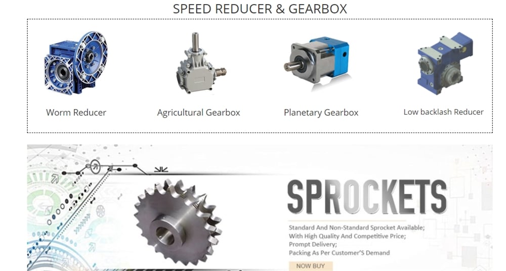
Gear Reducer is a mechanical transmission in many fields of the national financial system. The merchandise groups lined by the industry incorporate all sorts of gear reducer, planetary equipment reducer and worm gearbox, as effectively as a variety of specific transmission gadgets these kinds of as velocity escalating system, speed management Devices, like a variety of kinds of adaptable transmission units, this sort of as compound transmission. Merchandise and solutions in the field of metallurgy, nonferrous metals, coal, developing components, ships, h2o conservancy, electricity, construction machinerOur merchandise is well-liked exported to the United States, Germany, Australia, Russia, Spain, Hungary, Zimbabwe, Ukraine, Nigeria, Peru, Brazil, Center and South America, Thailand, Pakistan, Indonesia, far more than 60 nations and locations.y and petrochemical industries.
In all fields of countrywide economy and nationwide protection industry, gearbox items have a vast range of applications. Meals light market, electrical equipment, development equipment, metallurgy machinery, cement equipment, environmental protection machinery, electronic appliances, road building equipment, h2o conservancy machinery, chemical machinery, mining equipment, conveyor equipment, creating supplies machinery, rubber equipment, petroleum equipment and other industries have robust need of Reducer products.Chinese helical bevel speed reducer with electrical reduction gear motor reductor for conveyor.
Technologies
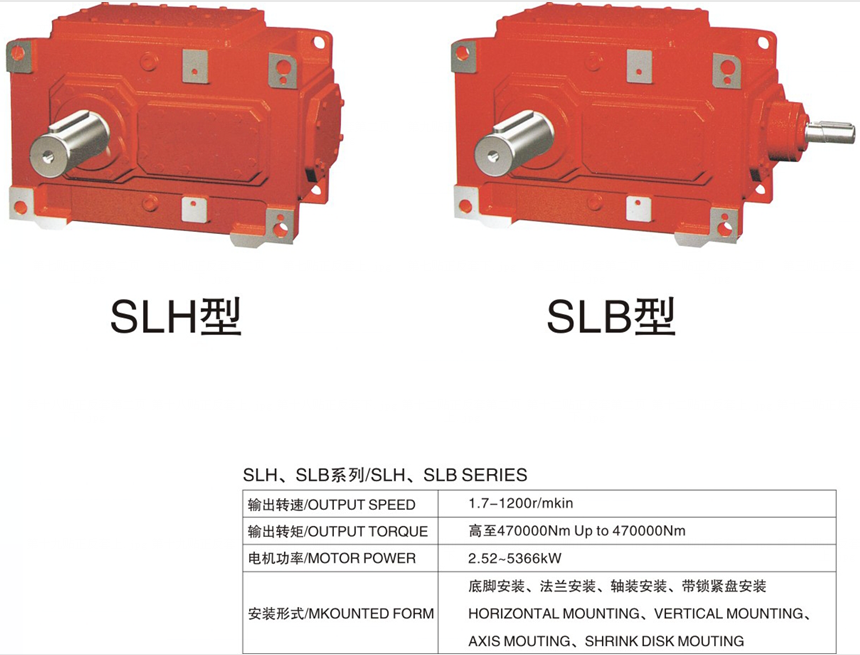
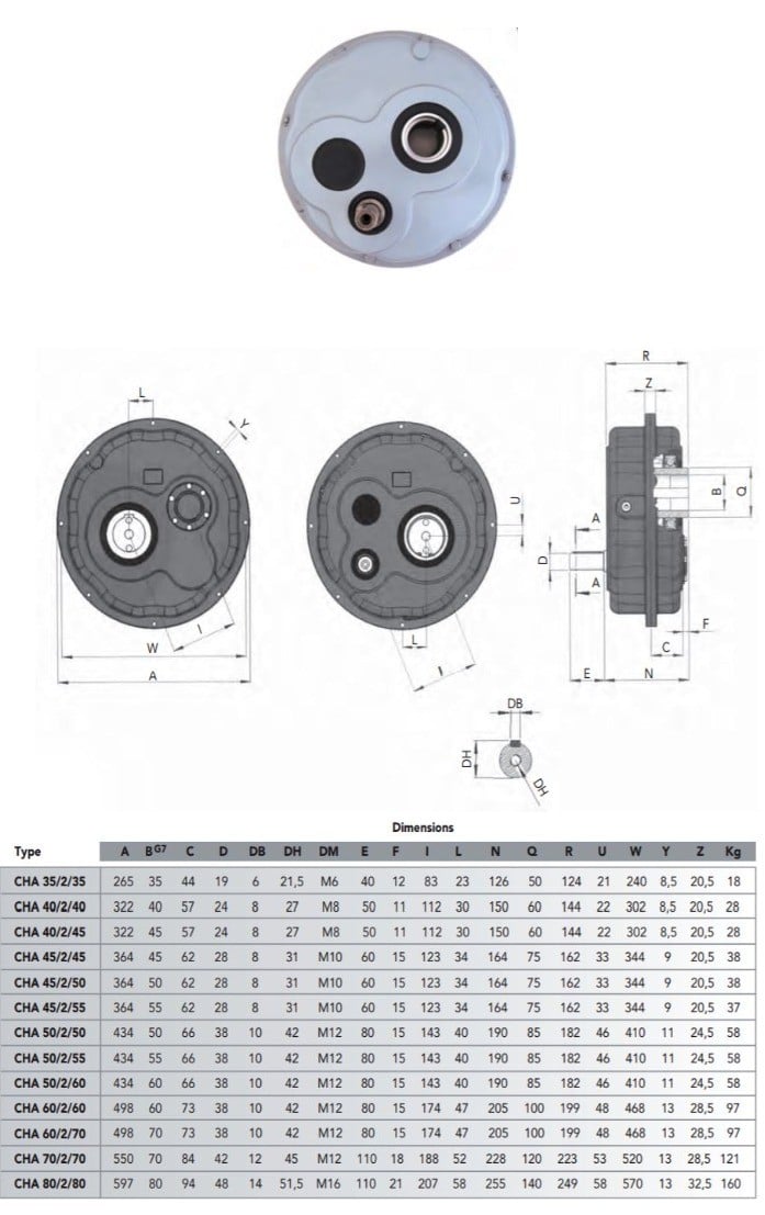
Packaging & Shipping and delivery
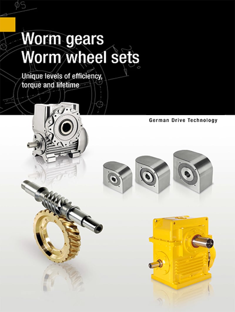
Company Details
Founded in 1995, HangZhou Ever-Electrical power Power machinery Co.,Ltd has 22 several years of reducer manufacturing experience and reliability. The company has professional engineer crew, sophisticated technological innovation production and competent employees, with located in HangZhou of ZheJiang province which has reliable industrial base and created transportation.
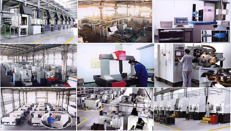
FAQ
1.Q:Are you the manufacturing unit or investing business?
A:We are the skilled Factory with 22 many years of knowledge.
2.Q:Can you customise according to our demands?
A:Of course, we can design nonstandard goods in accordance to customer’s drawing and sample.
3.Q:How extended is the supply date?
A:10-20 operating times.
4.Q:Where is your manufacturing facility?
A:We are in HangZhou of ZheJiang Province, you can get here by substantial velocity train or fly to Jinan.
Welcome to go to us!